


F-41
TROUBLESHOOTING AND REPAIR
F-41
POWER WAVE 455/POWER FEED 10
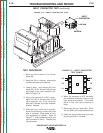
High voltage is present at primary of
Auxiliary Transformer.
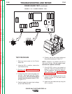
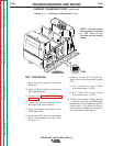
9. If the correct input voltage is applied to
the primary, and the secondary volt-
age(s) are not correct, the T1 trans-
former may be faulty.
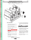
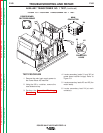
10. Install the case sides and top using the
3/8 in. nutdriver.
7. Carefully apply the correct input voltage
to the Power Wave 455 and check for
the correct secondary voltages per
Table F.3.
NOTE: The secondary voltages will vary if
the input line voltage varies.
8. If the correct secondary voltages are
present, the T1 auxiliary transformer is
functioning properly. If any of the sec-
ondary voltages are missing or low,
check to make certain the primary is
configured correctly for the input volt-
age applied. See wiring diagram.
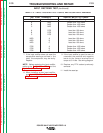
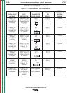
TABLE F.3 — SECONDARY VOLTAGES.
AUXILIARY TRANSFORMER NO. 1 TEST
(continued)
NORMAL EXPECTED
LEAD IDENTIFICATION VOLTAGE
X1 to X2 52 VAC
X3 to X5 115 VAC
X3 to X4 24 VAC
WARNING
Return to Section TOC Return to Section TOC Return to Section TOC Return to Section TOC
Return to Master TOC Return to Master TOC Return to Master TOC Return to Master TOC