


F-15
TROUBLESHOOTING AND REPAIR
F-15
POWER WAVE 455/POWER FEED 10
POWER FEED
Observe all Safety Guidelines detailed throughout this manual.
If for any reason you do not understand the test procedures or are unable to perform the tests/repairs safely, contact the Lincoln Electric
Service Department for technical troubleshooting assistance before you proceed. Call 216-383-2531 or 1-800-833-9353.
-----------------------------------------------------------------------------------------------------------------------------
CAUTION
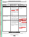
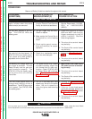
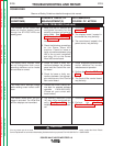
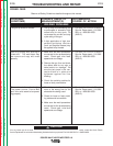
PROBLEMS
(SYMPTOMS)
POSSIBLE AREAS OF
MISADJUSTMENT(S)
RECOMMENDED
COURSE OF ACTION
The ammeter on the Control Box
does not function properly even
though the STATUS LEDs are
steady green.
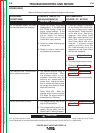
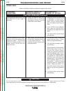
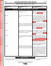
The display and/or indicator LEDs
do not change when their corre-
sponding switches and or knobs
are activated or turned.
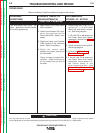
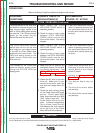
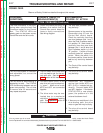
The mode and/or settings change
while welding under normal condi-
tions.
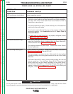
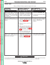
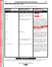
The feeder resets when the gun
trigger is activated. The LEDs blink
and the displays are intermittent.
1. Make sure the DIP switches are
configured correctly for the
welding process and polarity
being used. See
Setting DIP
Switches in the Wire Drive
in
the
Installation
section of this
manual.
2. Check the following connections
on the Power Wave 455
machine. Check for loose or
faulty connections between plug
J90 at the current transducer
and plug J21 on the Power
Wave 455 control board.
1. Check for loose or faulty con-
nections between the encoder
panel and the Control Box con-
trol board.
2. Check for loose or faulty con-
nections between the appropri-
ate switches and the Control
Box control board.
1. Contact the Lincoln Electric ser-
vice dept. for possible software
updates 1-800-833-9353.
(Please ref. your current soft-
ware number.)
1. The auxiliary reconnect (Lead
“A”) may not be configured cor-
rectly.
See Figure A.2.
in the
Installation Section of this man-
ual.
1. Perform the
Current Trans-
ducer Test.
2. The display board, located in
the control box, may be faulty.
3. The control board, located in the
power source, may be faulty.
1. Check suspected potentiometer
and/or switches for correct
resistances and operation.
2. Perform the
Encoder PC Board
Test.
3. The Control Box control board
may be faulty.
1. Perform the
Power Board Test
.
2. Perform the
Auxiliary
Transformer Test #1.
FUNCTION PROBLEMS (Continued)
Return to Section TOC Return to Section TOC Return to Section TOC Return to Section TOC
Return to Master TOC Return to Master TOC Return to Master TOC Return to Master TOC