


E-13
THEORY OF OPERATION
E-13
POWER WAVE 455/POWER FEED 10
the correct commands are transmitted to
the feed drive. The feed drive control board
then sends the signals to energize the
active components such as the solenoid
and wire drive motor. The tach feedback
signal is processed on the control board
which regulates the motor armature voltage
so as to maintain the required wire feed
speed.
When the gun trigger is pulled, the voltage
sense board relays the electrode sense sig-
nal to the input network receptacle for pro-
cessing by the Control Box.
The optional shutdown feature can be
implemented as a means of stopping the
wire feeding in the event that the water
cooler (if used) is not turned on.
The STATUS LED is designed to blink a red
and green code if a fault should occur.
There is one DIP switch bank located on the
wire drive control board. It is labeled S1
and is used to set gear ratios, arc polarity,
and for network identification purposes.
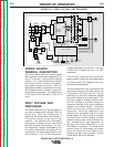
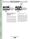
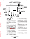
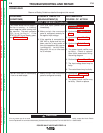
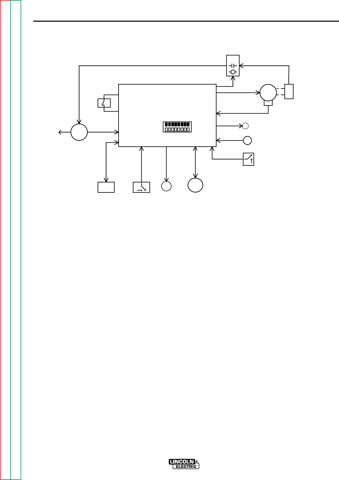
POWER FEED 10
FEED HEAD
The Power Feed 10 is a four roll, high per-
formance, digitally controlled, modular wire
feeder that operates on 40 VDC input
power. It is designed to be part of a modu-
lar, multi-process welding system. Refer to
Figure E.11.
Network communications, intelligence, PC
board input power, and arc voltage feed-
back is received and transmitted through
the input network receptacle. The internal
network connector plug is utilized when the
Control Box is mounted directly to the wire
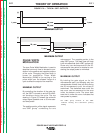
drive unit. See
System Diagram A
in this
section. The optional network output recep-
tacle is used when the system components
are connected in a daisy-chain fashion.
The feed drive control board processes the
information it receives from the various user
operated switches such as the gun trigger,
2-step/4-step, and cold inch switches and
sends this information to other system com-
ponents. This information is evaluated and
FIGURE E.11 — POWER FEED 10 FEED HEAD.
CONTROL BOARD
LEAD #67A
VOLTAGE
SENSE
LEAD #67
DRIVE
MOTOR
GEAR BOX
AND
CONDUCTOR
BLOCK
TACH
FEEDBACK
STATUS LED
2-STEP/
4-STEP
GUN TRIGGER AND
DUAL PROCEDURE
RECEPTACLE
TO POWER
SOURCE OR
CONTROL
BOX
DIP SWITCH
INPUT
NETWORK
RECEPTACLE
NETWORK
CONNECTOR
(INTERNAL)
COLD
INCH/
GAS
PURGE
GAS
SOLENOID
NETWORK
OUTPUT
RECEPTACLE
(OPTIONAL)
SHUTDOWN
Return to Section TOC Return to Section TOC Return to Section TOC Return to Section TOC
Return to Master TOC Return to Master TOC Return to Master TOC Return to Master TOC