


F-90
TROUBLESHOOTING AND REPAIR
F-90
POWER WAVE 455/POWER FEED 10
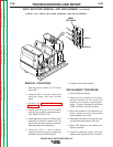
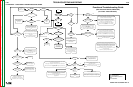
5. Using the 7/16 in. wrench, remove the
eight transformer leads from the rectifi-
er modules. Label the leads and take
note of lead placement for reassembly.
Note that each screw has two flat
washers and one lock washer.
6. Remove leads #220 and #290 from the
rectifier thermostat.
7. Using the 7/16 in. wrench, remove the
four nuts and associated washers from
the heatsink mounting bolts. The heat-
sink assembly can be removed by care-
fully sliding the assembly forward and
removing the mounting bolts.
RECTIFIER ASSEMBLY
REMOVAL PROCEDURE
1. Remove input power to the Power
Wave 455.
2. Using the 3/8 in. nutdriver, remove the
case top and sides.
3. Perform the
Capacitor Discharge
Procedure.
4. Using the 9/16 in. wrench, remove the
positive output lead from the rectifier
heatsink. Refer to Figure F.26.
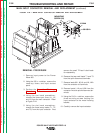
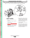
FIGURE F.26 — OUTPUT RECTIFIER AND MODULE REMOVAL AND REPLACEMENT.
TRANSFORMER
LEADS
RECTIFIER
MODULE
THERMOSTAT
HEATSINK
HEATSINK
MOUNT
BOLTS (4X)
POSITIVE
OUTPUT
LEAD
OUTPUT RECTIFIER AND MODULE REMOVAL AND REPLACEMENT
(continued)
Return to Section TOC Return to Section TOC Return to Section TOC Return to Section TOC
Return to Master TOC Return to Master TOC Return to Master TOC Return to Master TOC