


B-6
OPERATION
B-6
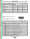
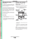
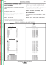
6. CV/GOUGE PANEL
The CV/Gouge Panel provides a fixed toggle switch
selection of two power source modes. The upper
position selects the generic CV/MIG mode from the
power source while the lower position selects the
GOUGE mode.
OPTIONAL PANELS
A number of Optional Features are available for use
with the Power Feed 10. Some Installation informa-
tion is provided in the
ACCESSORIES
section,
REFER TO THE INSTRUCTIONS THAT COME
WITH EACH KIT FOR DETAILED INFORMATION
REGARDING INSTALLATION.
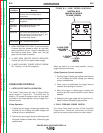
BOARD LEVEL ADJUSTMENTS
The control box motherboard provides the capability
to adjust some basic parameters as follows.
BURNBACK
The BURNBACK trimmer (R5) is provided as a basic
adjustment for burnback time. The range is 0.0 to
0.25 seconds, CCW limit is minimum, CW limit is
maximum. This value is overridden by any option
with the ability to independently adjust burnback.
ACCELERATION
See
DIP Switch setup
in the
Installation
section.
RUN IN
See
DIP Switch setup
in the
Installation
section.
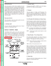
WELD MODE DESCRIPTIONS
CONSTANT VOLTAGE (CV/MIG)
For each wire feed speed, a corresponding voltage is
preprogrammed into the machine through special
softwares at the factory. This preprogrammed volt-
age is the best average voltage for the procedure at
the given wire feed speed. If the wire feed speed is
changed on the wire feeder, the voltage automatical-
ly changes with it.
In some cases, the operator may want to change the
preprogrammed voltages; for example, to compen-
sate for cable and fixture voltage drops. The preset
voltages can be adjusted on the wire feeder’s voltage
display. When a change is made to the voltage at
one wire feed speed, this change is applied to all
other wire feed speed settings. For example, if the
operator turns up the voltage by 10 percent, the
machine automatically increases the preset voltages
at all the other wire feed speeds by 10 percent. The
preset voltage, programmed at the factory, may be
changed with the wire feeder VOLTS adjustment.
ARC GOUGING
Arc gouging can be performed by choosing the arc
gouging weld mode. Doing so automatically ener-
gizes the output terminals on the Power Wave, mak-
ing the power source immediately ready to gouge.
The output current is set by the AMPS control on the
Power Weld wire feeder. The VOLTS/TRIM adjust-
ment has no effect in this mode.
The ARC CONTROL adjusts the arc force.
Increasing the ARC CONTROL setting increases the
arc force, making the arc more harsh but less likely
to stick. Decreasing the ARC CONTROL setting
decreases the arc force, making the arc softer and
smoother.
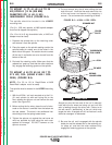
ELECTRODE ROUTING
The electrode supply may be either from reels,
Readi-Reels, spools, or bulk packaged drums or
reels. Observe the following precautions:
a. The electrode must be routed to the wire
drive unit so that the bends in the wire are at
a minimum, and also that the force required
to pull the wire from the reel into the wire
drive unit is kept at a minimum.
b. The electrode is “hot” when the gun trigger is
pressed and must be insulated from the
boom and structure.
c. If more than one wire feed unit shares the
same boom and are not sharing the some
power source output stud, their wire and
reels must be insulated from each other as
well as insulated from their mounting struc-
ture.
POWER WAVE 455/POWER FEED 10
Return to Section TOC Return to Section TOC Return to Section TOC Return to Section TOC
Return to Master TOC Return to Master TOC Return to Master TOC Return to Master TOC