


C-15
ACCESSORIES
C-15
The value of the active set up parameter is shown on
the MSP2 panel digital display. The value can be modi-
fied with the Set switch. The Set switch is an up/down
center-off momentary toggle switch. Moving the switch
bat up or down adjusts the displayed value in the cor-
responding direction. Holding the switch in either direc-
tion will cause the display to move quickly in the corre-
sponding direction until the switch is released, or the
upper or lower parameter limit is reached.
To energize the output studs in either CC/Stick mode,
the right Control/Display panel knob, labeled
Volts/Trim, must be used. The Volts/Trim knob must
be turned clockwise roughly a quarter revolution to
energize the output studs. (The Volts/trim display will
indicate ‘On’ when the studs are energized.)
Similarly, turning the knob a quarter turn counter-
clockwise de-energizes the output studs. If a CC/Stick
weld mode is entered through use of the Dual
Procedure, the studs will be in the same state as
when they were last used. If a CC/Stick weld mode is
entered through a Memory recall, the studs will be de-
energized.
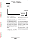
CONTROL BOX PANELS -- SET UP
CONTROLS DESCRIPTION
Certain large option panels can modify the set up
parameters Preflow, Run In, Arc Control, Burnback,
Postflow, and Crater. The meaning of those parame-
ters, and their maximum and minimum values, follows.
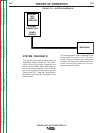
Preflow - Time delay after the trigger is pulled, but
before weld starts, during which shielding gas flows.
Weld start is defined as the time when both the power
source is energized and the Wire Drive begins feeding
wire. Adjustable from 0.0 (Off) to 2.5 seconds in 0.1s
increments.
Run In - Wire feed speed during arc starting. Wire
Drive will feed wire at the Run In speed for one sec-
ond, or until weld current flows. Low speed gear
range: Off (Run In speed equals weld wire feed
speed) or adjustable from 50 to 150 IPM (1.25 to 3.80
MPM). High speed gear range: Off (Run In speed
equals weld wire feed speed) or adjustable from 75 to
150 IPM (2.00 to 3.80 MPM). NOTE: Run In settings
over 150 IPM produce strange display values used for
troubleshooting and service. If encountered, reset Run
In to 150 IPM or less.
Arc Control - Unitless characteristic, also known as
Inductance or Wave Control. Allows operator to vary
the arc characteristics from “soft” to “harsh” in all weld
modes. Adjustable from -10.0 to 10.0 in increments of
0.1. Off (0.0) is nominal.
Burnback - Time delay after the trigger is released-
during which the power source remains energized but
the Wire Drive stops feeding wire. Adjustable from
0.00 (Off) to 0.25 seconds in 0.01 second increments.
Postflow - Time delay after burnback is complete,
during which shielding gas flows. Adjustable from 0.0
(Off) to 10.0 seconds in 0.1 second increments.
Crater - Used only when welding with the 4-Step trig-
ger mode. Can be set to Off or On. When On,
Adjustments can be made to WFS and Volts/Trim on
the Control/Display panel. These settings are then
used for ‘cratering’ when in the 4-Step trigger mode
(see explanation of 2 Step and 4 Step operation
below). When Off, ‘cratering’ is not possible.
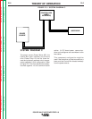
CONTROL BOX -- PC BOARD ADJUSTMENTS
The Control Box Mother board provides the capability
to adjust some wire feeding parameters as follows:
Acceleration: The motor acceleration can be varied
in five steps, from slow to fast. See “Setting DIP
Switches in the Control Box” section.
Burnback: For the options which cannot adjust the
Burnback set up parameter (CV/G and M panels) a
PC board adjustment (trimmer R5) is provided. The
range is 0.0 to 0.25 seconds, increasing in the clock-
wise direction. This is ignored by options which have
the ability to adjust Burnback (MX2 and MSP2 pan-
els).
Run In: For the options which cannot adjust the Run
In set up parameter (CV/G and M panels) a PC board
DIP switch setting is provided. In one position, the run
in speed will be the minimum Wire Drive WFS. At the
other setting, run in will occur at the same speed as
set on the WFS knob. This DIP switch setting is
ignored by options which have the ability to adjust
Run In (MX2 and MSP2 panels). See “Setting DIP
Switches in the Control Box” section.
POWER WAVE 455/POWER FEED 10
Return to Section TOC Return to Section TOC Return to Section TOC Return to Section TOC
Return to Master TOC Return to Master TOC Return to Master TOC Return to Master TOC