


E-3
THEORY OF OPERATION
E-3
POWER WAVE 455/POWER FEED 10
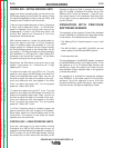
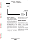
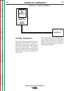
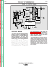
The communication cable is depicted by the
heavy black connector line. PC board
power, communications and intelligence
between the wire drive and combination
power source/Control Box unit are con-
veyed through this cable.
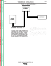
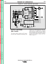
SYSTEM DIAGRAM B
This system utilizes two physical pieces of
equipment. Refer to Figure E.2. The combi-
nation Control Box (user interface) and
power source (Power Wave 455) make up
one of the circuit elements. This combina-
tion unit is coupled to the wire drive module
(Power Feed 10). Note the Control Box is
attached to and internally connected to the
power source.
FIGURE E.2 — SYSTEM DIAGRAM B.
CONTROL
BOX
(USER
INTERFACE)
POWER
SOURCE
INTERNAL
CONNECTION
WIRE DRIVE
Return to Section TOC Return to Section TOC Return to Section TOC Return to Section TOC
Return to Master TOC Return to Master TOC Return to Master TOC Return to Master TOC