


C-4
ACCESSORIES
C-4
POWER WAVE 455/POWER FEED 10
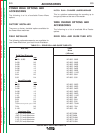
INPUT CABLE ASSEMBLIES
K1543 (Control Cable Only) - Consists of a 5-con-
ductor control cable with a 5-pin control cable plug,
without electrode cable, and is available in lengths of
10 ft, 15 ft, 20 ft, 50 ft, and 100 ft.
K1544 - Consists of a 5-conductor control cable with
a 5-pin control cable plug and a 3/0 electrode cable.
It is rated at 600 amps, 60% duty cycle and is avail-
able in lengths of 10 ft,15 ft, 20 ft, and 50 ft.
With input power disconnected from the power
source, install the input cable by performing the
following:
CABLE RECEPTACLES
K1548-1 RECEPTACLE KIT (INPUT AND
OUTPUT)
This kit contains the contents of both the K1549-1
and K1550-1 kits. Refer to the instructions for each,
below.
RECEPTACLE (OUTPUT)
Optional Output Connector installation into the
Control Box cabinet and/or into the feed head
enclosure.
Control Box Cabinet Procedure
1. Turn off power.
2. Remove the screws from the front of the lower
and middle option panels of the Control Box.
3. Tilt the option panels away from the front open-
ing of the Control Box cabinet. If the option panel
has an electrical connector, disconnect it from
the main printed circuit board (note connection
point for re-connection later). Remove the option
panel and set aside.
4. Remove the plastic plug (black) from the left hole
in the bottom of the Control Box cabinet and
store it in the bottom of the Control Box cabinet
for future use, should the Optional Output
Connector be removed.
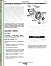
5. Place the Optional Output Connector
(Amphenol) through the hole opened by the pre-
vious step (place from the inside, out). Rotate
the Optional Output Connector so its aligning
key is positioned to the front of the Control Box
cabinet. Fasten the Optional Output Connector
to the bottom wall of the Control Box cabinet with
the four screws provided.
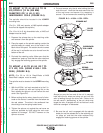
6. Secure the choke (large circular component of
the Optional Output Connector) by inserting its
leads into the white nylon clip located near the
Optional Output Connector on the back wall of
the Control Box cabinet. Insert the choke leads
only.
7. The Optional Output Connector has two internal
connectors, a four pin, and a single lead connec-
tor. Connect the four pin connector to the
unused four pin connector on the main printed
circuit board. Connect the single lead connector
to a similar connector found on a lead nearby
that branches out of the Control Box wiring har-
ness.
8. Re-install the lower and middle option panels by
reversing the removal process. While re-
installing the option panels, ensure clearance
between Optional Output Connector compo-
nents, Control Box wiring harness, and option
panel harness (if any).
Return to Section TOC Return to Section TOC Return to Section TOC Return to Section TOC
Return to Master TOC Return to Master TOC Return to Master TOC Return to Master TOC