


F-17
TROUBLESHOOTING AND REPAIR
F-17
POWER WAVE 455/POWER FEED 10
POWER FEED
Observe all Safety Guidelines detailed throughout this manual.
If for any reason you do not understand the test procedures or are unable to perform the tests/repairs safely, contact the Lincoln Electric
Service Department for technical troubleshooting assistance before you proceed. Call 216-383-2531 or 1-800-833-9353.
-----------------------------------------------------------------------------------------------------------------------------
CAUTION
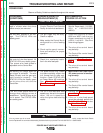
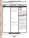
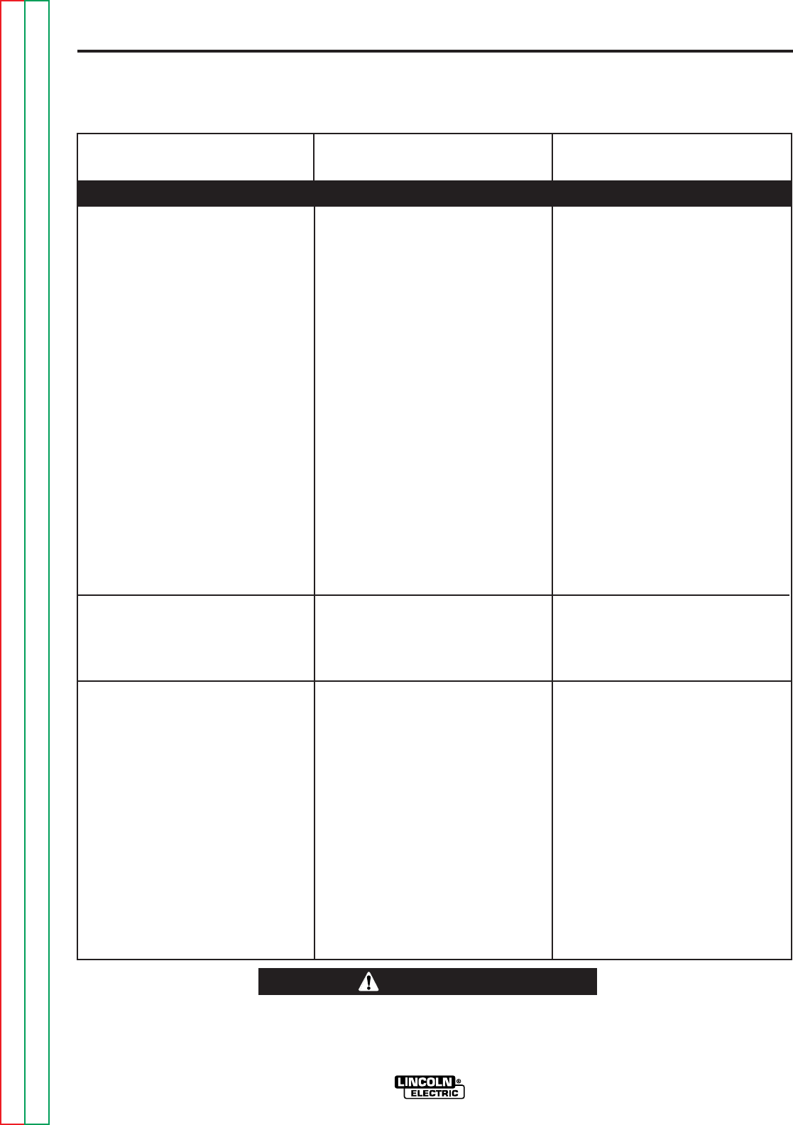
PROBLEMS
(SYMPTOMS)
POSSIBLE AREAS OF
MISADJUSTMENT(S)
RECOMMENDED
COURSE OF ACTION
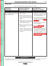
The Dual Procedure is not func-
tioning when using the local Dual
Procedure switch on the Control
Box. The STATUS LEDs are
steady green on the power source,
Control Box and wire drive units.
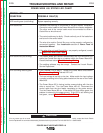
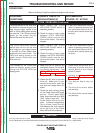
The wire feed speed is consistent
and adjustable, but runs at the
wrong speed.
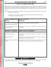
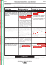
The unit shuts off while welding or
attempting to weld. The STATUS
LED is alternating between red and
green every second. The unit tries
to recover after 30 seconds and
may repeat sequence.
1. Check the leads and plug J5
between the switch and the
Control Box control board for
loose or faulty connections.
See wiring diagram.
1. The DIP switch on the wire drive
unit may not be set for the cor-
rect gear ratio. See the
Instal-
lation
section of this manual.
1. The shut down circuit in the
wire drive unit may be electrical-
ly “open”. Make sure leads
#570 and #571 are connected
together.
2. The drive motor may be over
loaded due to a mechanial
restriction in the wire feeding
path. See
Operation
section of
this manual.
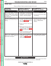
1. The local dual procedure switch
may be faulty.
Remove power to the machine.
Disconnect plug J5 from the
Control Box control board.
Check for continuity (less than
one ohm) between pins 1 and 7
when the Dual Procedure switch
is in position “A”. Next check for
continuity (less than one ohm)
between pins 1 and 8 when the
Dual Procedure switch is in the
“B” position. If either of these
continuity tests fail, replace the
switch. When the switch is in
the center position, there should
not be any continuity between
pins.
2. The Control Box control board
may be faulty.
1. The wire drive control board
may be faulty.
1. Disconnect any shutdown
device from leads #570 and
#571 (0.25 in. insulated tab ter-
minals). Connect leads #570
and #571 together. If the feeder
STATUS LED is now steady
green, the problem is in the
external shutdown circuit.
2. If there are no restrictions in the
wire feeding path, the drive
motor or gear box may be faulty.
3. The wire drive control board
may be faulty.
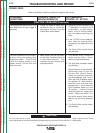
FUNCTION PROBLEMS (Continued)
Return to Section TOC Return to Section TOC Return to Section TOC Return to Section TOC
Return to Master TOC Return to Master TOC Return to Master TOC Return to Master TOC