


A-7
INSTALLATION
POWER WAVE 455/POWER FEED 10
A-7
CABLE CONNECTIONS
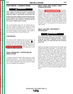
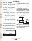
CONTROL CABLE CONNECTIONS
• All system control cables are the same but can
vary in length.
• All control cables can be connected end to end to
extend their length.
• All system equipment must be connected to a
control cable.
Welding systems using the Power Feed 10 offer pre-
viously unprecedented flexibility in the connection of
system components. This system uses the same
type of control cable between each of the system
components. Connections can be “daisy chained”
from one system component to another. Since com-
munication over the control cables is done by a
robust communications network, the order of connec-
tion of the components makes no difference. The
cables can be connected anywhere that there is a
mating connector. See the flexible connections part
of this section for more details.
NOTE: Maximum cable length between any two
nodes is 250 feet.
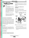
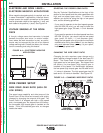
TYPICAL BENCH FEEDER CONNECTION
Control cable is connected from Power Source (PS)
to Feed Head (FH). If the Control Box is separated
from the FH, a control cable will connect from the PS
to the control box, which will have two control cable
connectors. This could be the control box or the FH
control box depending on how the units were sepa-
rated. A second control cable would be connected
from the second connector on the control box to the
other FH control box.
TYPICAL BOOM FEEDER CONNECTION
Control cable is connected from PS to the control
box. A second control cable would be connected
from the second connector on the control box to the
FH control box.
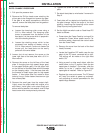
FLEXIBLE CONNECTION POSSIBILITIES
By using connector kits, a second connector can be
added to the Control box or the FH. This allows the
user to connect equipment types together in any
order.
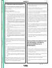
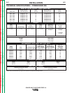
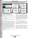
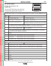
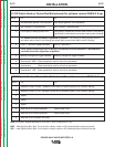
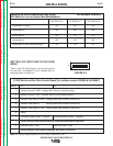
FIGURE A.2 — CONNECTION DIAGRAM ON RECONNECT/INPUT ACCESS DOOR.
200-208V
220-230V
380-415V
440-460V
200-208V
220-230V
VOLTAGE=220-230V
220-230V
200-208V
220-230V
380-415V
440-460V
200-208V
U / L1
440-460V
380-415V
.
inspecting or servicing machine.
Do not operate with covers
.
removed.
Do not touch electrically live parts.
.
Only qualified persons should install,
use or service this equipment.
.
'A'
'A'
VOLTAGE=380-415V
'A'
S23847
VOLTAGE=200-208V
THE LINCOLN ELECTRIC CO. CLEVELAND, OHIO U.S.A.
A
'A'
VOLTAGE=440-460V
CR1
W / L3
V / L2
380-415V
440-460V
Disconnect input power before
INPUT SUPPLY CONNECTION DIAGRAM
Return to Section TOC Return to Section TOC Return to Section TOC Return to Section TOC
Return to Master TOC Return to Master TOC Return to Master TOC Return to Master TOC