


TROUBLESHOOTING AND REPAIR
F-94
POWER WAVE 455/POWER FEED 10
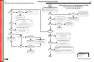
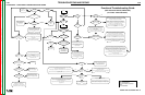
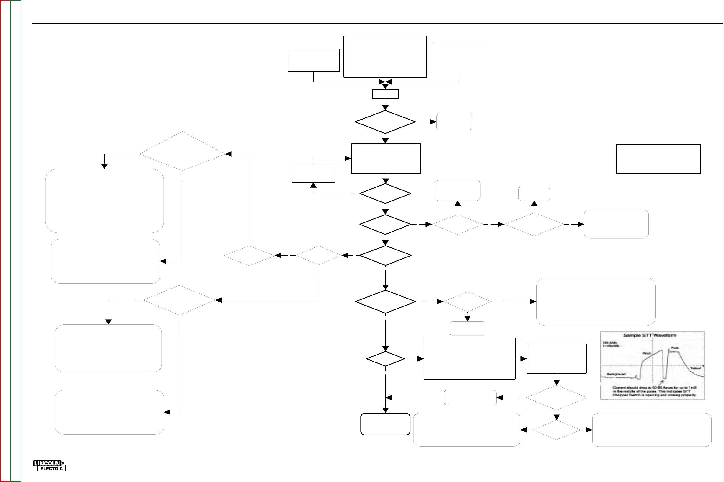
FLOWCHART - PERFORMANCE TROUBLESHOOTING GUIDE
Turn On
Performance Test Configuration (USE STD
STUD)**
GMAW (.045 Steel - 3/8" Plate)
Mode = 5
WFS =400 ipm
Voltage = 28V
Gas =90/10 ArCO2
Arc Control= 0
** Configuration may be altered based on available
materials. A spray procedure was selected for
Alternate CC Configuration:
Grid Load (300A / 30V)
Mode = 200
Current = 300
Arc Control = 0
Alternate CV Configuration:
Grid Load (300A / 30V)
Mode = 201
Voltage = 30V
Arc Control = 0
Note: Mode 201 requires an
electrode sense lead (67).
All Status Lights green?
UI functional with no
errors displayed? FH
functional?
See Functional
Troubleshooting
Guide
Activate output (trigger the welding
output).
Using the appropiate measuring
equipment, compare the Actual Current,
Voltage, and WFS to the readings
displayed on the UI
Do you get output
from the machine
(can you weld)?
Actual vs Displayed
WFS:
+/-10 ipm?**
Actual vs Displayed
Voltage:
+/-1 Volt?**
Actual vs Displayed
Current:
+/- 10 Amps?**
Increase or Decrease the
output settings as
required to achieve a
stable output.
The system is monitoring and
controlling WFS, Voltage,
and Current correctly.
Performance checks OK.
Y
Y
Y
Y
Y
Y
N
Y
N
**Note: The accuracy of measuring equipment
plays a significant role.Generally speaking,
meters of reasonable accuracy should give
readings within the stated limits. The intent
here is to establish proper performance, not
absolute accuracy.
Motor running full
speed regardless of
WFS setting?
Does FH gear ratio
dipswitch setting match
pinion gear size?
Perform tachometer test.
Repair / replace as
necessary.
Correct FH
Dipswitch
settin
g
.
Check for proper Drive Roll tension.
Check for proper Drive Rolls.
Verify software is correct version
(PF-10 vs.PF-11).
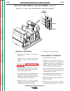
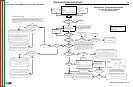
ALL VOLTAGE MEASUREMENTS SHOULD BE MADE
AT THE SOURCE OF THE VOLTAGE FEEDBACK.
The source of voltage feedback is mode dependent. Mode
200 senses voltage from the output studs of the machine.
Modes 5 and 201 sense from the Conductor Block on the
feeder to the negative stud of the machine, unless the
Voltage Sense Plug (P26) is removed from the Control PC
Bd., inwhich case the remote work sense plug is used
instead of the negative stud.
Test being
performed in Mode
200?
Perform the Voltage
Sense PC Board Test.
Under load
as defined
previously:
Check for
actual voltage
at the PS
Control PC
Bd., from P20-8
to P20-2
(P20
-
8to
P20-4 if usin
g
a remote work
sense lead)
The Power Source Control PC Board is interpreting voltage correctly, but
there is a bad or incorrect connection in the feedback path.
Check to make sure the weld polarity matches the Electrode Sense
Polarity dipswitch in the FH (SW-7). The default setting is electrode
positive.
Check connections in the entire electrode sense path (wire #67) from the
2 pin output connector on the Voltage Sense PC Board, through the FH
w
irin
g
harness, control cable
(
s
)
, UI wirin
g
harness
(
if s
y
stem is
configured with the UI between the FH and PS), and up to P20-8 on the
Control PC Board inside of the PS.
Check the work sense path (wire #202) from P20-2 on the PS Control PC
Board to the Work Stud, or (wire #21) from P20-4 to the remote work
sense lead depending on the configuration.
The PS Control PC Board is NOT interpreting voltage correctly.
On "-3" and higher vintage PS Control PC Boards the Voltage
feedback can be calibrated. Perform the "Voltage Calibration
Procedure".
If unable to calibrate, replace the Control PC Board. Please note the
statement regarding test meter accuracy, and follow all applicable
board replacement procedures when replacing this board.
OK
Matches Display
Value +/- 1V
Does not match
Display Value +/- 1V
NN
Under load as defined
previously: Check for actual
voltage at the PS Control PC
Bd., from P20-6 to P20-2.
The Power Source Control PC Board is interpreting voltage
correctly, but there is a bad connection in the feedback path.
Check connections in the electrode sense path (wire #206) from
P20-6 on the Control PC Board to the electrode(+) stud inside of
the PS.
Check the work sense path (wire #202) from P20-2 on the Control
PC Board to the Work Stud.
The PS Control PC Board is NOT interpreting voltage correctly.
On "-3" and higher vintage PS Control PC Boards the Voltage
feedback can be calibrated. Perform the "Voltage Calibration
Procedure".
If unable to calibrate, replace the Control PC Board. Please note the
statement regarding test meter accuracy, and follow all applicable
board replacement procedures when replacing this board.
Matches Display
Value +/- 1V
Does not match
Display Value +/- 1V
Y
Y
N N Y
N
Perform the PS
Current Transducer
Test
The PS Control PC Board is NOT interpreting current correctly.
Check the connections at P21 on the Control PC Board. Particularly the
signal pins (1 and 6).
Depending on the magnitude of the descrepency, the current feedback
can be calibrated. Perform the "Current Calibration Procedure".
If unable to calibrate, and the connections are OK, replace the Control PC
Board. Please note the statement regarding test meter accuracy, and
follow all applicable board replacement procedures when replacing this
board.
Replace the current
Transducer.
N Pass
Fail
Performance Troubleshooting Guide
(Semi Automatic PW-455, PW455/STT)
Key:
PS = Power Source
UI = User Interface (Control
Box)
FH = Feed Head
STT Machine?
N
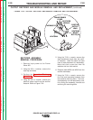
STT Performance Test Configuration (USE STT STUD)**
GMAW (.045 Steel - 1/4" Plate)
Mode = 117
WFS =170 ipm
Trim = 1.00
Gas =CO2
Arc Control= 0
** Configuration may be altered based on available
materials, but basic waveshape should remain the same.
!!CANNOT BE TESTED WITH STATIC GRID LOAD!!
Using the Arc Scope function in
Wave Designer / Wave Surfer, or
an oscilloscope equiped with a
current probe, capture an STT
waveform, and compare it to the
sample STT waveform (shown at
ri
g
ht
)
.
Are the wave shapes
similar, and does current
drop in the middle of the
pulse as indicated?
Does the machine
noodle weld ( low output)?
The STT Chopper PC Board appears to be "open".
Check for 18Vac at J10 pins 1 & 4 on the STT Chopper Board.
Check for loose or broken connections. Inspect the PC board for physical
damage
Perform the STT Chopper Board Test.
The STT Chopper PC Board appears to be shorted, and therefore,
the resulting current waveform does not drop in the middle of the
pulse as indicated in the Sample STT Waveform
Disconnect J10 from the STT Chopper PC Board, and make
another test weld. If the same symptoms result, perform the STT
chopper PCBD test. If the machine noodle welds, the problem is
related to the control signal from the Control PC Board.
The STT portion of the system
is operating properly
Y
N
Y
YN
A NOTE ON VOLTAGE SENSING:
All CV and Pulse modes utilize the electrode sense lead (lead #67) built into the control cable.
As with any sense lead it's performance is only as good as the worst connection.
For diagnostic purposes, an external sense lead can be used to bypass the entire electrode
sense network. This can be accomplished by removing the front cover of the PW-455, and
connecting a lead (20 AWG minimum) from pin 5 of the exposed 6 pin UI molex connector (P6),
to the feedplate on the feeder.
(For Codes 10555 and Below)
F-94
Return to Section TOC Return to Section TOC Return to Section TOC Return to Section TOC
Return to Master TOC Return to Master TOC Return to Master TOC Return to Master TOC