


F-40
TROUBLESHOOTING AND REPAIR
F-40
POWER WAVE 455/POWER FEED 10
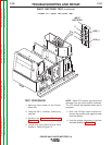
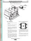
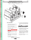
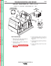
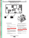
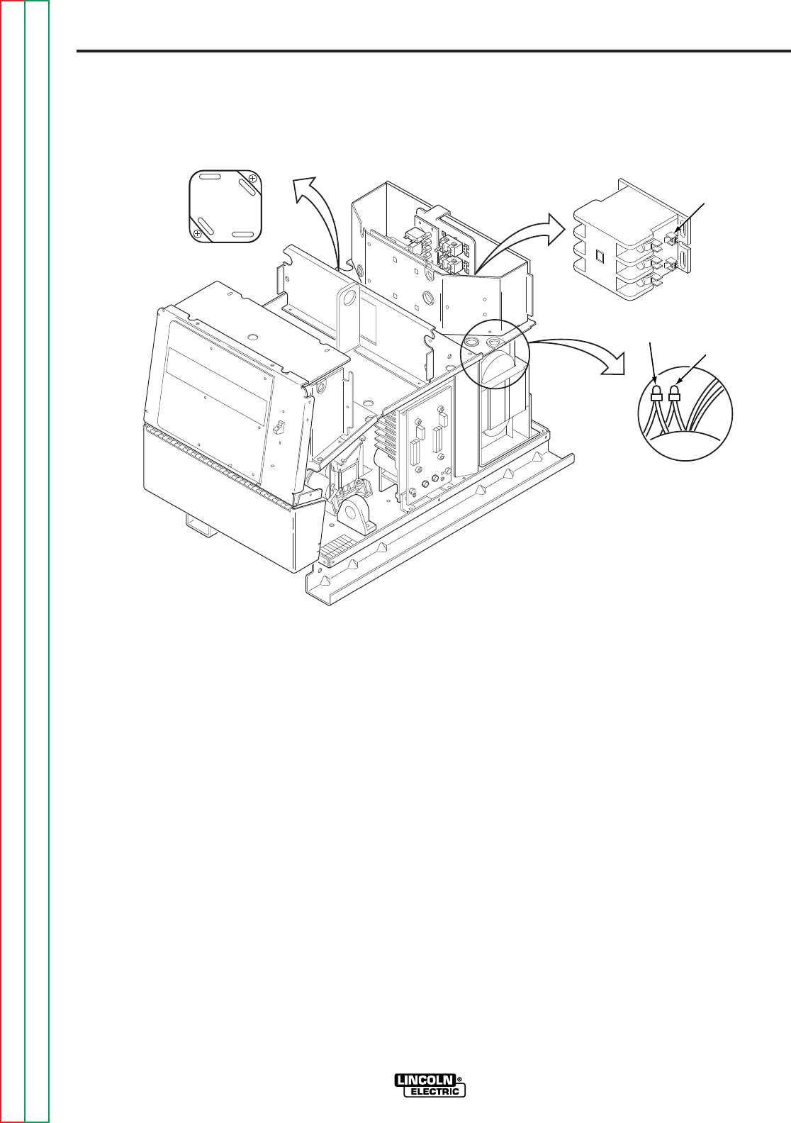
4. Locate secondary leads X1 and X2 (at
power board rectifier bridge). Refer to
Figure F.9.
5. Locate secondary leads X3 and X5 (fan
motor leads).
6. Locate secondary lead X4 (at main
contactor).
TEST PROCEDURE
1. Remove the main input supply power to
the Power Wave 455 machine.
2. Using the 3/8 in. nutdriver, remove the
case sides and top.
3. Perform the
Capacitor Discharge
Procedure.
FIGURE F.9 — AUXILIARY TRANSFORMER NO. 1 TEST.
FAN MOTOR
LEADS
X4
MAIN
CONTACTOR
POWER BOARD
RECTIFIER BRIDGE
X1
X2
X3
X5
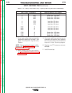
AUXILIARY TRANSFORMER NO. 1 TEST
(continued)
Return to Section TOC Return to Section TOC Return to Section TOC Return to Section TOC
Return to Master TOC Return to Master TOC Return to Master TOC Return to Master TOC