


A-5
INSTALLATION
POWER WAVE 455/POWER FEED 10
A-5
3. Loosen the four screws inside the Control Box
located along the sides of the back of the Control
Box, two near the bottom and two near the mid-
dle.
4. Push the Control Box upwards and then pull the
Control Box away from the wire drive.
5. Remove plug button taped to inside of Control
Box and insert it into hole on front panel of wire
drive.
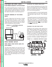
BOOM MOUNTING
If you wish to convert to a boom mount, the follow-
ing components are required to complete the conver-
sion process:
Item 1 K1549-1 Receptacle
Item 2 K1550-1 Receptacle
Assemble the components above as follows:
1. Remove plug button and mount item 1 to the left
hole in the bottom of the Control Box.
2. Remove and save plug button and mount item 2
to the right hole in the bottom of the Control Box.
3. Insert connector from item 1 into either 4-pin
connector on Control Box motherboard.
4. Insert 6-pin connector that went to wire drive unit
into item 2.
5. Connect sense lead from item 1 to sense lead
from 6-pin connector that went to wire drive unit.
6. Replace all option panels removed from front of
Control Box.
7. Place plug button saved in step 2 into hole in
back panel of Control Box.
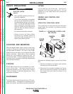
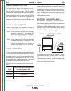
CONTROL BOX POWER SOURCE MOUNTING
The Power Feed Control Box can be directly mount-
ed on the front of the power source. If this control
location is preferred, complete the following steps to
mount Control Box on the power source:
1. Remove the bottom and center option panels
from the front of the Control Box.
2. Mount Control Box to the power source, follow-
ing the instructions supplied with that specific
power source.
3. If the Control Box has an input Amphenol con-
nector mounted on right side of bottom, then dis-
connect it’s 6-pin electrical connector from the
input connector inside the Control Box.
NOTE: This input connector no longer functions.
4. Connect 6-pin connector that comes out of the
back of the Control Box to the 6 pin connector.
(See specific power source instructions.)
5. 67 sense lead from left bottom connector (if pre-
sent) should be connected to 67 sense lead con-
nection from 6-pin connector from motherboard.
6. Replace all option panels removed from front of
Control Box.
Return to Section TOC Return to Section TOC Return to Section TOC Return to Section TOC
Return to Master TOC Return to Master TOC Return to Master TOC Return to Master TOC