


B-5
OPERATION
B-5
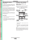
Cold feed function:
When this switch is held in the up position, the unit
automatically feeds wire, but does not activate output
to the power source or gas solenoid. The speed of
this cold feed is factory preset to 200 IPM. It can be
adjusted while the switch is held up, by rotating the
WFS encoder knob on the Control Box. Note that
this cold feed speed is independent of WFS or run in
speeds. When the cold feed switch is released, the
cold feed value is memorized for the next time cold
feed is activated.
Gas purge function:
When this switch is held in the down position only the
gas solenoid valve is energized.
3. STATUS LIGHT
A two color light that indicates system errors. Normal
operation is a steady green light.
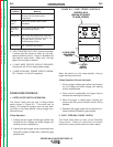
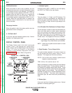
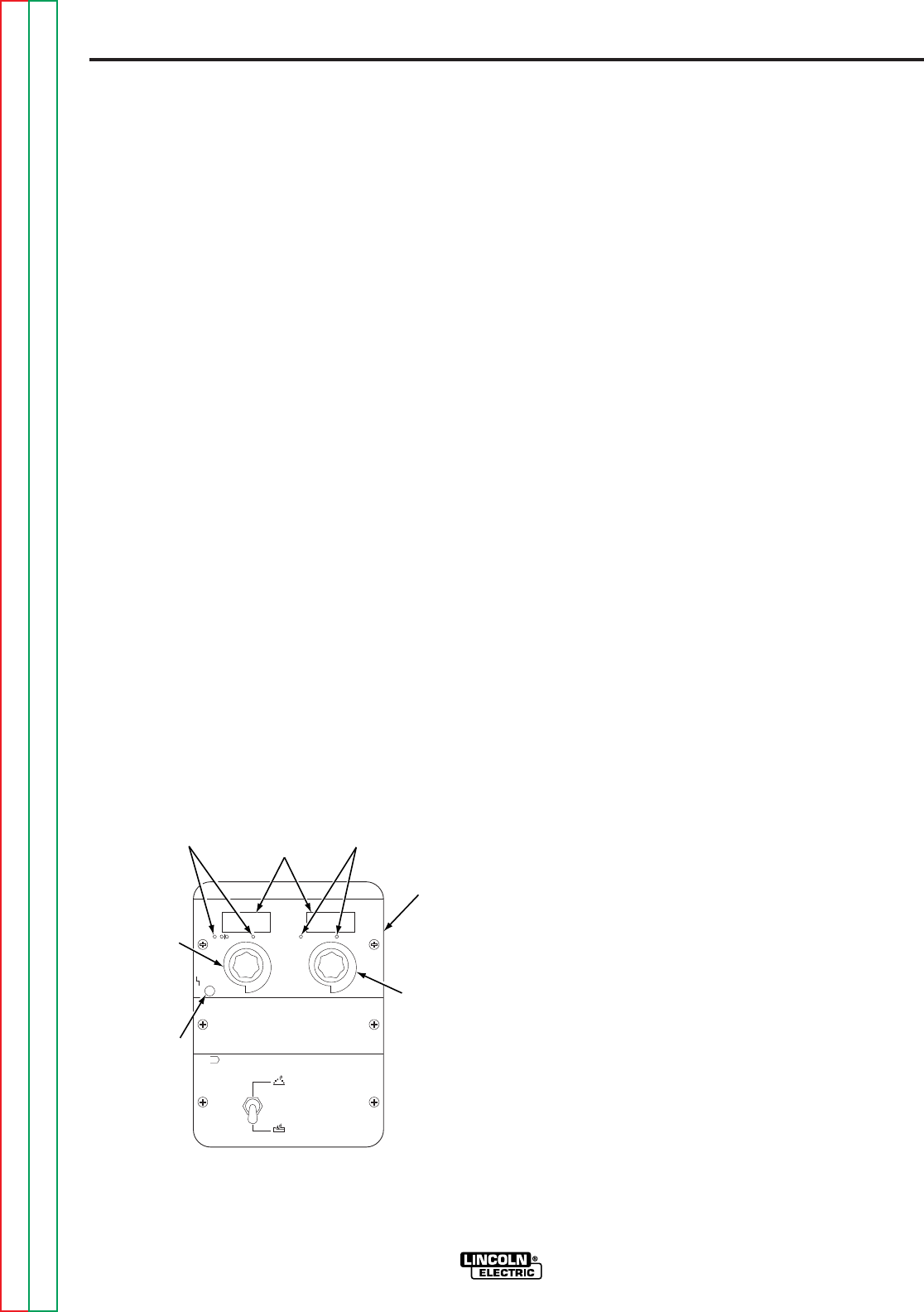
DISPLAY CONTROL PANEL
The Display Control panel is the main input to the
system. From it, the operator can control WFS,
amps, voltage, and trim depending on the active weld
mode. It is also the location of the Status
indicator, a multicolored diagnostic LED (see
Troubleshooting
section). Refer to Figure B.3.
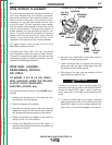
FIGURE B.3 — CONTROL BOX.
1. Indicator Lights:
Indicates either WFS or AMPS for the left display,
and VOLTS or TRIM for the right display.
2. Displays:
Two extra bright, 3 1/2 digit, red LED displays. The
values of the active parameters are displayed, as
defined by their associated indicators. The left dis-
play is for WFS or Amps, while the right display is for
voltage or trim.
3. Left Encoder-Wire Feed Speed or Output Amps:
The left encoder is used to adjust the parameters for
either wire feed speed or output amps, dependent
upon the process and weld mode being used.
Rotating the encoder knob CCW decreases the num-
ber value, while rotating the knob CW increases the
number value. The ranges and limits are as follows:
WFS - Low Range: 50 to 800 IPM (1.25 to 19.99 MPM)
High Range: 75 to 1200 IPM (2.0 to 30.5 MPM)
AMPS - Limited by the power source based on mode
and process.
4. Right Encoder - Trim or Output Volts:
The right encoder operates in the same manner as
the left except that either output Volts or Trim is
adjusted. The ranges and limits are as follows:
VOLTS - 00.0 to 99.9 volts, limited by power source
based on mode and process.
TRIM - 0.50 to 1.50, nominal value is 1.00
When not welding (no output current flow) the displays
reflect the preset values. During welding (output cur-
rent flowing) the displays depict actual values. These
actual values are held for a period of five seconds after
welding (output current) ceases. This hold feature is
canceled if a trigger pull or encoder adjustment occurs
during the hold time. The actual value displayed is
dependent upon the weld mode and process being
used.
5. Status light:
A two color light that indicates system errors. Normal
operation is a steady green light.
POWER WAVE 455/POWER FEED 10
GOUGE
STATUS
WFS AMPS VOLTS
TRIM
A V T
CV/MIG
WELD MODE
m
1. INDICATOR
LIGHTS
2. DISPLAYS
1. INDICATOR
LIGHTS
3. WFS/
AMPS
ENCODER
5. STATUS
LIGHT
6. CV/GOUGE PANEL
BLANK PANEL
DISPLAY
CONTROL
PANEL
4. VOLTS/
TRIM
ENCODER
Return to Section TOC Return to Section TOC Return to Section TOC Return to Section TOC
Return to Master TOC Return to Master TOC Return to Master TOC Return to Master TOC