


F-66
TROUBLESHOOTING AND REPAIR
F-66
POWER WAVE 455/POWER FEED 10
REPLACEMENT PROCEDURE
1. Carefully screw the Hall Effect device
into the gear box assembly until it gen-
tly “bottoms out” on the rotary magnet
inside.
2. Unscrew the Hall Effect device 1/2 turn
from the rotary magnet. Tighten the
locking nut to 8 in/lbs.
3. Thread the J4 leads through the vertical
baffle and install cable ties where
appropriate.
4. Connect plug J4 into the control board.
5. Install the wire feeder cover using the
3/8 in. nutdriver.
REMOVAL PROCEDURE
1. Remove input power to the wire feeder.
2. Using the 3/8 in. nutdriver, remove the
case cover.
3. Locate the tach assembly on the top of
the gear box. Refer to Figure F.19.
4. Locate and remove plug J4 from the
control board.
5. Thread plug J4 and associated leads
through the vertical baffle. Cut any
necessary cable ties.
6. Using the 9/16 in. wrench, loosen the
locking nut on the Hall Effect device.
7. Carefully unscrew the Hall Effect device
from the gear box assembly.
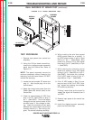
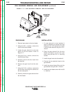
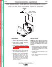
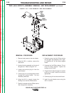
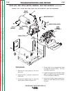
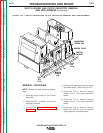
FIGURE F.19 — TACH REMOVAL AND REPLACEMENT.
LOCK
NUT
HALL
EFFECT
DEVICE
TACH
ASSEMBLY
TACH (HALL EFFECT) ASSEMBLY REMOVAL AND REPLACEMENT
(continued)
Return to Section TOC Return to Section TOC Return to Section TOC Return to Section TOC
Return to Master TOC Return to Master TOC Return to Master TOC Return to Master TOC