


SECTION E-1
THEORY OF OPERATION
SECTION E-1
POWER WAVE 455/POWER FEED 10
TABLE OF CONTENTS
-THEORY OF OPERATION SECTION-
Theory of Operation ................................................................................................................................. Section E
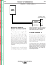
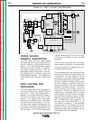
Modular Inverter Based Welding System........................................................................................... E-2
System Diagram A............................................................................................................................. E-2
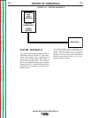
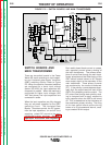
System Diagram B............................................................................................................................. E-3
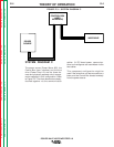
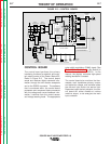
System Diagram C............................................................................................................................. E-4
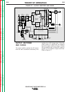
Power Source General Description.................................................................................................... E-5
Input Voltage and Precharge ............................................................................................................. E-5
Switch Boards and Main Transformer................................................................................................ E-6
Control Board..................................................................................................................................... E-7
Output Rectifier and Choke................................................................................................................ E-8
Thermal Protection............................................................................................................................. E-9
Protective Circuits.............................................................................................................................. E-9
Over Current Protection..................................................................................................................... E-9
Under/Over Voltage Protection.......................................................................................................... E-9
Insulated Gate Bipolar Transistor (IGBT) Operation.......................................................................... E-10
Pulse Width Modulation ..................................................................................................................... E-11
Minimum Output .......................................................................................................................... E-11
Maximum Output ......................................................................................................................... E-11
Control Box (User Interface) .............................................................................................................. E-12
Power Feed 10 Feed Head................................................................................................................ E-13
Return to Master TOC Return to Master TOC Return to Master TOC Return to Master TOC