


F-77
TROUBLESHOOTING AND REPAIR
F-77
POWER WAVE 455/POWER FEED 10
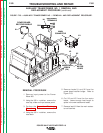
4. Connect two molex plugs and black
and white wires with quick disconnects
to the power PC board.
5. Connect the eight molex plugs to the
control PC board.
6. Install the PC board compartment cover
using the 3/8 in. nutdriver.
7. Install the case top and sides using the
3/8 in. nutdriver.
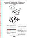
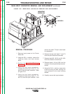
INSTALLATION PROCEDURE
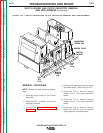
1. Install either the power or control board
to the PC board assembly and secure it
in place using the Phillips head mount-
ing screws.
2. Carefully slide the power and control
PC board assembly into place, making
sure to clear the lead harnesses on the
right and left side of the PC board com-
partment.
3. Secure the rear of the control box in
place using two screws and the 3/8 in.
nutdriver.
CONTROL OR POWER BOARD REMOVAL AND REPLACEMENT
(continued)
Return to Section TOC Return to Section TOC Return to Section TOC Return to Section TOC
Return to Master TOC Return to Master TOC Return to Master TOC Return to Master TOC