


B-7
OPERATION
B-7
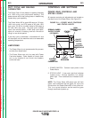
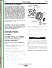
WIRE SPINDLE PLACEMENT
The reel stand provides two mounting locations for
the 2 inch diameter wire reel spindle to accommo-
date various reel sizes. Each mounting location con-
sists of a tube in the center of the reel stand, and a
locating pin on the right side (viewed from the front)
of the reel stand. The bolt, used with a plain washer
and lock washer, slides through the tube from the left
side of the reel stand. The large plain washer is
placed between the wire spindle hub and the reel
stand. The bolt should be threaded into the wire
spindle such that the locating pin aligns with the
largest of the three holes (the hole that is not
recessed) in the back side of the wire spindle base.
The upper location must be used for 50 to 60 lb
Readi-Reels, spools and coils.
For smaller coils (44 lb, 30 lb, 10 lb, etc.), the spindle
can be placed in either the upper or lower location.
The goal is to make the wire path from the coil to the
incoming wire guide as straight as possible. This will
optimize wire feeding performance.
WIRE REEL LOADING -
READI-REELS, SPOOLS
OR COILS
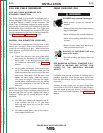
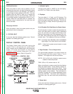
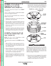
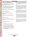
TO MOUNT A 30 LB (14 KG) READI-
REEL PACKAGE (USING THE MOLDED
PLASTIC K363-P READI-REEL
ADAPTER) (FIGURE B.4):
The spindle should be located in the LOWER mount-
ing hole.
1. Depress the release bar on the retaining collar
and remove it from the spindle.
2. Place the adapter on the spindle.
3. Re-install the retaining collar. Make sure that the
release bar “pops up” and that the collar retainers
fully engage the retaining groove on the spindle.
4. Rotate the spindle and adapter so the retaining
spring is at the 12 o'clock position.
5. Position the Readi-Reel so that it will rotate in a
direction when feeding so as to be de-reeled from
the bottom of the coil.
FIGURE B.4 — READI-REEL MOUNTING.
6. Set one of the Readi-Reel inside cage wires on
the slot in the retaining spring tab.
7. Lower the Readi-Reel to depress the retaining
spring and align the other inside cage wires with
the grooves in the molded adapter.
8. Slide cage all the way onto the adapter until the
retaining spring “pops up” fully.
Check to be sure the retaining spring has fully
returned to the locking position and has SECURELY
locked the Readi-Reel cage in place. Retaining
spring must rest on the cage, not the welding elec-
trode.
-----------------------------------------------------------
9. To remove Readi-Reel from adapter, depress
retaining spring tab with thumb while pulling the
Readi-Reel cage from the molded adapter with
both hands. Do not remove adapter from spindle.
POWER WAVE 455/POWER FEED 10
CAUTION
2 IN. O.D.
SPINDLE
ADAPTER
RETAINING
SPRING
BRAKE
HOLDING
PIN
GROOVES
READI-REEL
INSIDE
CAGE
WIRES
RELEASE
BAR
RETAINING
COLLAR
Return to Section TOC Return to Section TOC Return to Section TOC Return to Section TOC
Return to Master TOC Return to Master TOC Return to Master TOC Return to Master TOC