


F-81
TROUBLESHOOTING AND REPAIR
F-81
POWER WAVE 455/POWER FEED 10
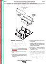
and the machine base using the 3/8 in.
nutdriver.
3. Install the primary leads H2, H3, H4,
and H5 to the reconnect terminals on
the reconnect panel.
4. Connect primary lead H1 to circuit
breaker CB4.
5. Splice the new transformer lead with
the X3 lead connected to the input
board.
6. Connect lead X4 to the main contactor
coil terminal.
7. Splice the new transformer fan leads to
the fan motor leads X3 and X5.
8. Connect leads X1 and X2 to the power
board rectifier bridge.
9. Reposition any wire leads and install
wire ties as necessary.
10. Install the case back using the 3/8 in.
nutdriver.
11. Install the case top, sides, and input
access panel using the 3/8 in. nutdriver.
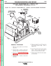
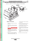
8. Cut the X3 lead that is connected to the
input board. Leave enough lead length
to splice in the new transformer lead.
9. Locate, label, and remove primary lead
H1 from circuit breaker CB4.
10. Label and remove primary leads H2,
H3, H4, and H5 from the reconnect ter-
minals on the reconnect panel. Note
lead placement for reassembly.
11. Using the 3/8 in. nutdriver, remove the
two mounting screws that hold the
transformer to the fan baffle and the
machine base.
12. Cut any necessary cable ties and clear
the leads.
13. Carefully remove the transformer from
the Power Wave 455.
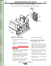
REPLACEMENT PROCEDURE
1. Carefully place the transformer into the
Power Wave 455.
2. Install the two mounting screws that
hold the transformer to the fan baffle
AUXILIARY TRANSFORMER NO. 1 REMOVAL AND
REPLACEMENT PROCEDURE
(continued)
Return to Section TOC Return to Section TOC Return to Section TOC Return to Section TOC
Return to Master TOC Return to Master TOC Return to Master TOC Return to Master TOC