


F-54
TROUBLESHOOTING AND REPAIR
F-54
POWER WAVE 455/POWER FEED 10
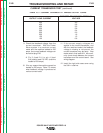
5. With the gun trigger activated and the
motor running, check the feedback volt-
age at plug J4 pin #2 (blue wire) posi-
tive to pin #3 (black wire) negative.
Normal feedback voltage is approxi-
mately 5 VDC. If the correct supply volt-
age is present and the feedback volt-
age is missing, the tach unit may be
faulty. With the motor NOT running,
the feedback voltage may be either 0 or
10 VDC depending upon where the
motor stopped.
6. Remove input power from the wire
feeder unit.
7. Install the wire feeder cover with the 3/8
in. nutdriver.
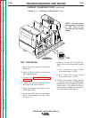
TEST PROCEDURE
1. Remove input power from the wire
feeder unit.
2. Using the 3/8 in. nutdriver, remove the
cover from the wire feeder.
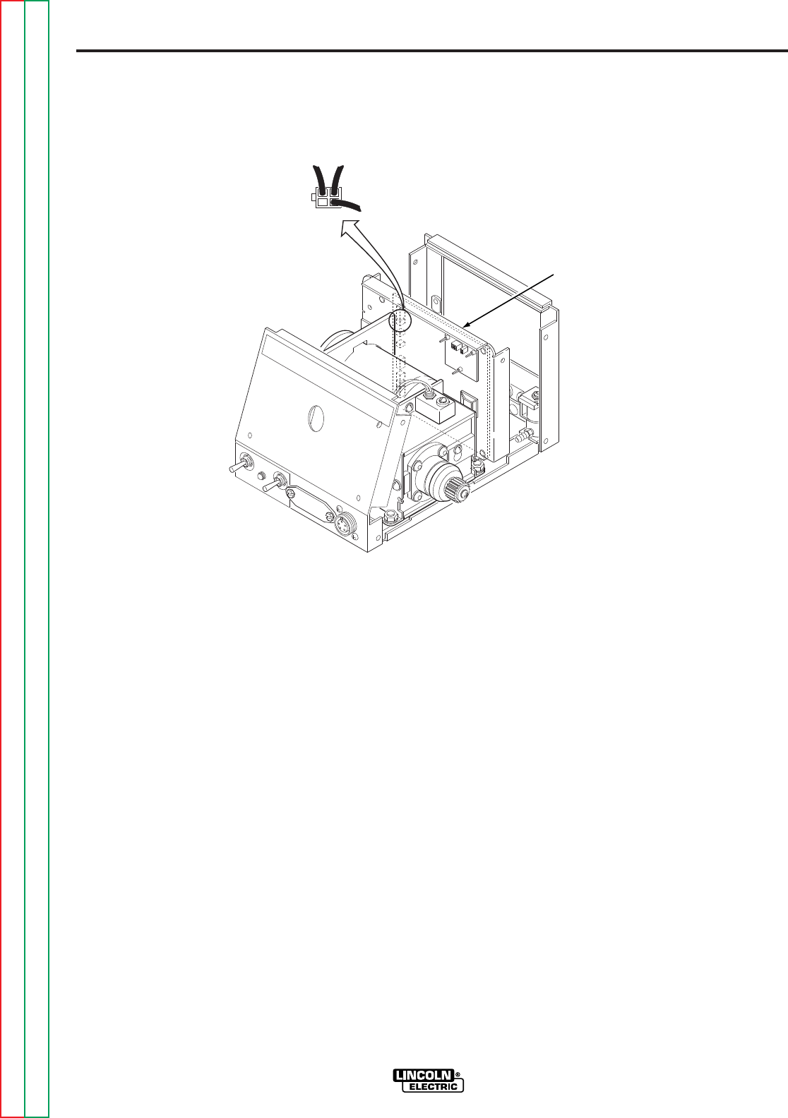
3. Locate plug J4 on the control board.
Refer to Figure F.13. Do NOT remove
the plug from the control board.
4. Apply the correct input power (from the
Power Wave 455 control cable) to the
wire feeder unit and check for approxi-
mately 12 VDC from pin #1 (red wire)
positive to pin #3 (black wire) negative.
This is the supply voltage from the con-
trol board to the tach feedback unit. If
the 12 VDC is missing or not correct,
the wire feeder control board may be
faulty. Also check for loose or faulty
wires and connections.
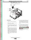
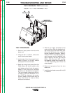
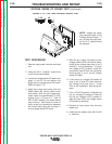
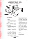
FIGURE F.13 — TACH FEEDBACK TEST.
WIRE FEED
CONTROL BOARD
#3
BLACK
#1
RED
#2
(BLUE)
J4
TACH FEEDBACK TEST
(continued)
Return to Section TOC Return to Section TOC Return to Section TOC Return to Section TOC
Return to Master TOC Return to Master TOC Return to Master TOC Return to Master TOC