


C-11
ACCESSORIES
C-11
Mode Selection
The MODE SELECT switch is a momentary large
three position toggle switch that defaults to the center
(off) position. Moving the switch up advances the
mode indicator in the upward direction, down
advances it in the downward direction. Holding the
switch in either direction will result in the indicator
advancing at a high rate of speed in that direction,
until the switch is released. When the indicator
reaches its upper or lower limit, advancing ceases
until the direction of the switch is changed.
Parameter Selection
The PARAMETER SELECT switch is a momentary
large three position toggle switch that defaults to the
center (off) position. Moving the switch up advances
the parameter indicator in the upward direction, down
advances it in the downward direction. Holding the
switch in either direction will result in the indicator
advancing at a high rate of speed in that direction,
until the switch is released. When the indicator
reaches its upper or lower limit, advancing ceases
until the direction of the switch is changed.
Parameter Adjustment
The value of the active parameter, as defined by the
parameter indicator, is displayed on the parameter
display. The PARAMETER SET switch is a momen-
tary large three position toggle switch that defaults to
the center (off) position. Moving the switch bat up
advances the displayed value in the positive direc-
tion, down advances it in the negative direction.
Holding the switch in either direction will result in the
displayed value advancing at a high rate of speed in
that direction, until the switch is released. When the
indicator reaches its upper or lower limit, advancing
ceases until the direction of the switch is changed.
Installation is as follows:
1. Turn off power.
2. Remove the two screws from the front of the
blank option panel at the location you choose to
install your new option (bottom) of the Control
Box cabinet. Save the screws, discard the old
panel or save for future use.
3. Tilt the new option panel away from the front
opening of the Control Box cabinet. Plug the
electrical connector into the proper connector on
the right side of the main printed circuit board
(12 pin). Make sure the connector latches in
place.
4. Position the new panel, taking care not to dam-
age the connections on the back.
5. Align the screw holes, replace the two screws
and tighten.
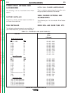
K1542-8 MSP PANEL (LARGE PANEL)
The MSP Panel provides a selection of numerous
process specific and generic power source modes. In
addition, it provides for the adjustment of the follow-
ing parameters: PREFLOW, RUN IN, ARC CON-
TROL, BURNBACK, POSTFLOW, and SPOT time.
Only one parameter, as defined by the parameter
indicator, may be displayed and adjusted at a time.
Description
Indicator Lights - Red LED’s indicate the active para-
meter being displayed.
Display - 3 1/2 digit, red LED display. Displays the
value or status of the active parameter.
Parameter Ranges
WELD MODE -
Adjustable per mode schedule.
PREFLOW -
0.0 to 2.5 seconds (0.1 sec. increments).
RUN IN -
Low Range: 50 to 150 IPM (1.25 to 3.80 MPM).
High Range: 75 to 150 IPM (2.00 to 3.80 MPM).
ARC CONTROL -
Trim (-10.0) to (+10.0) , (0) is nominal.
BURNBACK -
0.0 to 0.25 sec. (0.01 sec. increments).
POSTFLOW -
0.0 to 2.5 sec. (0.1 sec. increments).
SPOT -
0 to 25 sec. (0.1 sec. increments).
POWER WAVE 455/POWER FEED 10
Return to Section TOC Return to Section TOC Return to Section TOC Return to Section TOC
Return to Master TOC Return to Master TOC Return to Master TOC Return to Master TOC