


C-10
ACCESSORIES
C-10
Constant Voltage (CV/MIG and CV/Flux Cored)
Procedures
When in this mode, the ARC CONTROL adjusts the
inductance. (This adjustment is often referred to as
“pinch”. Inductance is inversely proportional to
pinch.) Increasing the ARC CONTROL setting
decreases the inductance, which results in the arc
getting colder and pinched tighter. Decreasing the
ARC CONTROL setting increases the inductance,
which results in the arc getting wider (reduced pinch).
Installation is as follows:
1. Turn off power.
2. Remove the two screws from the front of the
blank option panel at the location you choose to
install your new option (bottom) of the Control
Box cabinet. Save the screws, discard the old
panel or save for future use.
3. Tilt the new option panel away from the front
opening of the Control Box cabinet. Plug the
electrical connector into the proper connector on
the right side of the main printed circuit board (12
pin). Make sure the connector latches in place.
4. Position the new panel, taking care not to dam-
age the connections on the back.
5. Align the screw holes, replace the two screws
and tighten.
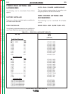
K1542-7 MX PANEL (LARGE PANEL)
The MX Panel provides a selection of four power
source modes. In addition, it provides for the adjust-
ment of the following parameters: PREFLOW, RUN
IN, ARC CONTROL, BURNBACK, POSTFLOW, and
SPOT time.
Descriptions
Indicator Lights - Extra bright red LED’s indicate the
mode and active parameter being displayed.
Display - Displays the value or status of the active
parameter.
Available Modes - CV/MIG
CV/ FLUX CORED
CC/STICK CRISP
CC/STICK SOFT
Due to the nature of the system, the following feature
is required for safety reasons. Upon entering any
constant current (CC) mode, the right encoder,
labeled VOLTS, TRIM, on the Display/Control Panel
acts as a “soft” contactor switch. The encoder knob
must be turned CW at least 45° to activate the output
(turning CCW 45° deactivates the output). This pre-
vents the output from inadvertently becoming “hot”
when scrolling through the weld modes. The excep-
tion to this rule is when the weld mode is entered by
a change in procedure (using a memory panel such
as the K1542-9 Memory/Dual Procedure panel). In
this case, the state of the contactor is recalled as it
was left when the procedure was exited.
In the CC modes, the output current is set by the
AMPS control, and the VOLTS/TRIM adjustment has
no effect in this mode. In this mode, the ARC
CONTROL adjusts the arc force. Increasing the ARC
CONTROL setting increases the arc force, making
the arc more harsh but less likely to stick. Decreasing
the ARC CONTROL setting decreases the arc force,
making the arc softer and smoother.
Parameter Ranges
PREFLOW -
0.0 to 2.5 seconds (0.1 sec. increments).
RUN IN -
Low Range: 50 to 150 IPM (1.25 to 3.80 MPM).
High Range: 75 to 150 IPM (2.00 to 3.80 MPM).
ARC CONTROL -
Trim (-10.0) to (+10.0) , (0) is nominal.
BURNBACK -
0.0 to 0.25 sec. (0.01 sec. increments).
POSTFLOW -
0.0 to 2.5 sec. (0.1 sec. increments).
SPOT -
0 to 25 sec. (0.1 sec. increments).
POWER WAVE 455/POWER FEED 10
Return to Section TOC Return to Section TOC Return to Section TOC Return to Section TOC
Return to Master TOC Return to Master TOC Return to Master TOC Return to Master TOC