


C-16
ACCESSORIES
C-16
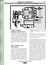
CONTROL BOX -- SETTING OPERATING LIMITS
Upper and lower operating limits can be set for the
WFS/Amps setting and the Volts/Trim setting. Doing
so requires knowledge of how to set the limits, and
access to the PC board in the Control Box.
There are two independent sets of limits, Procedure
A limits and Procedure B limits. If a DP/M door
option is installed, the A and B limits must be set
independently. If there is no DP/M door option, the
Control Box defaults to Procedure A, and only
Procedure A limits can be set.
With system power on, select the weld mode for
which you want to set limits. If a Dual Procedure
option is installed, select the procedure A. Turn the
system power off. Remove the two screws holding
the Control/Display panel to the Control Box, but do
not unplug it. Tilt the panel down to allow access to
DIP switches S1-1, S2-6 and S2-7. (See “Setting DIP
Switches in the Control Box” section.) Do not allow
the panel to hang by the wiring harness.
Determine if the Wire Drive is set up for low or high
speed. If low speed, S1-1 should be off. If high
speed, set S1-1 to on.
To adjust the lower limit, set S2-6 to on. Turn the
power on and adjust the WFS/Amps and Volts/Trim
knobs to the desired lower limits. Note: You will not
be able to adjust the lower limit outside of the mini-
mum and maximum wire feed speed of the Wire
Drive, nor above the upper limit. Turn the system
power off. Return S2-6 to off.
To adjust the upper limit, set S2-7 to on. Turn the
power on and adjust the WFS/Amps and Volts/Trim
knobs to the desired upper limits. Note: You will not
be able to adjust the upper limit outside of the mini-
mum and maximum wire feed speed of the Wire
Drive, nor below the lower limit. Turn the system
power off. Return S2-7 to off.
If a Dual Procedure panel is installed, repeat the
above procedure with the Procedure B selected.
When done, attach the Control/Display panel to the
Control Box. The machine is now ready for normal
operation with the new limits.
CONTROL BOX -- USING OPERATING LIMITS
Once set, limits apply to all weld modes. Limiting
Procedure A to 200 to 300 inches per minute, for
example, limits the ability of the operator to adjust his
WFS in pulse, CV and FCAW weld modes. Limiting
the Volts to 23.0 to 24.5 would limit the ability of the
operator to adjust his Volts in synergic and non-syn-
ergic CV modes. Procedure B could be set up with
different limits. Limits are absolute -- they will over-
ride values stored in the memories. Note that limits
do not apply to set up parameters, such a Preflow
and Arc Control.
OPERATION WITH PREVIOUS
SOFTWARE VERSION
The operation of the previous Control Box software
version (S24004-2) is different than described earlier
in this section. The differences are as follows:
• The Memory/Dual Procedure panel is not a valid
option.
• The MX (K1542-1) and MSP (K1542-8) are are
used in place of the MX2 and MSP2 options.
• Limits cannot be set.
The key difference in the MX/MSP panels, compared
to the MX2/MSP2 panels, is the Spot function. In the
old software, a 0.1 to 2.5 second Spot function was
available on these two panels. No Crater function
was available (Crater replaced Spot in the graphics
on these two panels).
An upgrade kit is available to change the software
from S24004-2 to the latest version of Control Box
software. Once the upgrade is done, the Dual
Procedure/ Memory panel becomes a valid option,
limits can be set, and Spot is replaced by Crater.
POWER WAVE 455/POWER FEED 10
Return to Section TOC Return to Section TOC Return to Section TOC Return to Section TOC
Return to Master TOC Return to Master TOC Return to Master TOC Return to Master TOC