


F-38
TROUBLESHOOTING AND REPAIR
F-38
POWER WAVE 455/POWER FEED 10
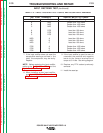
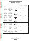
8. If 115 VAC is not present between pins
#1 and #4, check the associated leads
and plugs for loose or faulty connec-
tions.
High voltage is present at plug P80.
9. Carefully test for the correct AC input
voltage applied to the primary windings
at plug P80. See wiring diagram.
10. If the correct AC input voltage is
applied to the primary of the Auxiliary
Transformer No. 2 and the secondary
voltage is NOT correct, the transformer
may be faulty. Replace.
11. Install the left and right case sides
using the 3/8 in. nutdriver.
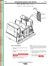
TEST PROCEDURE
1. Remove the main input supply power to
the Power Wave 455 machine.
2. Remove any load that may be connect-
ed to the 115 VAC receptacle.
3. Using the 3/8 in. nutdriver, remove the
left and right case sides.
4. Perform the
Capacitor Discharge
Procedure.
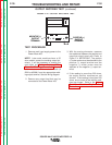
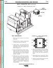
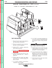
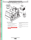
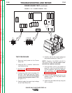
5. Locate plugs P80 and P81 at the
Auxiliary Transformer No. 2. Refer to
Figure F.8.
6. Carefully apply the correct input power
and check for 115 VAC at plug P81
pins #1 and #4.
7. If 115 VAC is present, the Auxiliary
Transformer No. 2 is good.
FIGURE F.8 — AUXILIARY TRANSFORMER NO. 2 TEST.
4
6
P80
1
2
3
1 4
P81
AUXILIARY TRANSFORMER NO. 2 TEST
(continued)
WARNING
Return to Section TOC Return to Section TOC Return to Section TOC Return to Section TOC
Return to Master TOC Return to Master TOC Return to Master TOC Return to Master TOC