


104 Chapter 2
Performance Verification Tests
13. Input Attenuation Switching Uncertainty
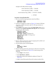
7. Preset the synthesized signal generator (Blue Key, Special, 0, 0) and
set the controls as follows:
FREQUENCY, 50 MHz
AMPLITUDE
, 12 dBm
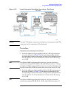
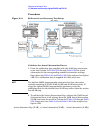
8. Set the 1 dB step attenuator to 5 dB attenuation. Set the 10 dB step
attenuator to 50 dB. Refer to the Agilent 11713A attenuator switch
driver manual for information on manually controlling a
programmable step attenuator.
9. Press
Peak Search (or Search) on the analyzer.
10.Adjust the amplitude of the synthesized signal generator until the
marker amplitude of the analyzer reads
−57 dBm± 0.1 dB.
75
Ω Input only: Adjust the amplitude of the synthesized signal
generator until the marker of the analyzer reads
−8.2 dBmV ± 0.1 dB.
NOTE Do not adjust the amplitude of the synthesized signal generator after
the reference is established.
11.On the analyzer, press
Peak Search (or Search), Marker, Delta.
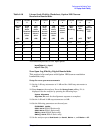
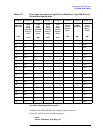
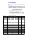
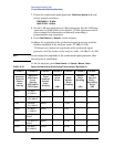
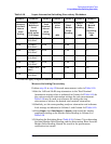
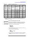
Table 2-19 Input Attenuation Switching Uncertainty Worksheet
Column 1 Column 2 Column 3 Column 4 Column 5 Column 6 Column 7
Analyzer
Internal
Attenu-
ation
Setting
Analyzer
Reference
Level
Setting
50 W Input/
75 W Input
Total
Nominal
Attenu-
ation
Setting
Attenu-
ation
Error
(dB)
Ideal
Marker
Delta
Reading
Marker
Delta
Reading
(dB)
Test
Record
Entry –
Switching
Error
(dB)
10 dB –55 dBm /
–6.2 dBmV
55 dB 0 0 dB 0 Ref
0 dB –65 dBm /
–16.2 dBmV
65 dB
−10 dB 1)
5 dB –60 dBm /
–11.2 dBmV
60 dB
−5 dB 2)
15 dB –50 dBm /
–1.2 dBmV
50 dB 5 dB 3)
20 dB –45 dBm / 3.8
dBmV
45 dB 10 dB 4)
25 dB –40 dBm / 8.8
dBmV
40 dB 15 dB 5)
30 dB –35 dBm /
13.8 dBmV
35 dB 20 dB 6)