


166 Chapter 2
Performance Verification Tests
22. Frequency Response: Agilent E4401B and E4411B
Measuring Frequency Response, 100 kHz to 1.5 GHz
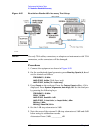
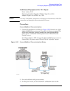
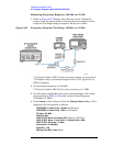
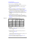
1. Refer to Figure 2-27. Remove the reference sensor (Channel A
sensor) from the power splitter. Connect the power splitter to the
analyzer 50
Ω Input using an adapter. Do not use a cable.
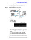
Figure 2-27 Frequency Response Test Setup, 100 kHz to 1.5 GHz
75
Ω inputs, Option 1DP: Connect the power splitter to the analyzer
75
Ω Input using a mechanical adapter and a 75 Ω, Type-N(m) to
BNC(m) adapter.
2. Set the source frequency to 100 kHz:
75
Ω inputs, Option 1DP: Set the source frequency to 1 MHz.
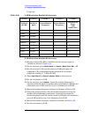
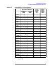
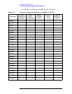
3. Set the source amplitude to the value corresponding to the source
power setting in Table 2-41 for the current source frequency
(100 kHz or 1 MHz).
4. Press
Preset on the analyzer. Press the Factory Preset softkey, if it is
displayed. Set the controls as follows:
FREQUENCY, Center Freq, 100 kHz (50 Ω Input)
FREQUENCY, Center Freq, 1 MHz (75 Ω Input)
CF Step, 100 MHz
SPAN, 20 kHz
AMPLITUDE, More, Int Preamp (Off)
(Option 1DS only)
AMPLITUDE, More, Y Axis Units (or Amptd Units), dBm
AMPLITUDE
, Ref Level, –5 dBm
Attenuation, 10 dB (Man)
Scale/Div, 1 dB
BW/Avg, Res BW, 3 kHz
(Man)