


Chapter 2 109
Performance Verification Tests
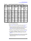
14. Reference Level Accuracy: Agilent E4401B and E4411B
Example for 50 dB attenuator setting:
Log Scale, Analog Bandwidths
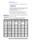
1. Set the synthesized signal generator controls as follows:
FREQUENCY, 50 MHz
AMPLITUDE
, 12 dBm
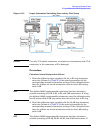
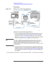
2. Connect the equipment as shown in Figure 2-14. Set the 10 dB step
attenuator to 20 dB attenuation and the 1 dB step attenuator to
5 dB attenuation.
3. Press
Preset on the analyzer. Press the Factory Preset softkey, if it is
displayed. Press
System, Alignments, Auto Align, Off. Set the analyzer
by pressing the following keys:
FREQUENCY, 50 MHz
Attenuation
, 10 dB (Man)
AMPLITUDE, –25 dBm (50 Ω Input only)
AMPLITUDE, 28.75 dBmV (75 Ω Input only)
Scale/Div, 1dB
SPAN
, 50 kHz
BW/Avg, 3 kHz
Video BW, 30 Hz
4. Set the 1 dB step attenuator to place the signal peak 1 to 3 dB (1 to 3
divisions) below the reference level.
5. On the analyzer, press the following keys:
Single
Peak Search
(or Search)
Marker, Delta
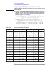
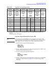
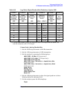
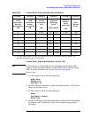
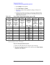
6. Set the 10 dB step attenuator and analyzer reference level according
to Column 1 and Column 4 of Table 2-20. At each setting, do the
following:
a. Press
Single on the analyzer.
b. Press
Peak Search (or Search).
c. Record the marker delta amplitude reading in Column 5 of
Table 2-20.
d. Add the Actual Attenuation Step to the analyzer marker delta
Actual Attenuation 50 dB()50.08 dB=
Actual Attenuation 20 dB()19.85 dB=
Actual Attenuator Step 50 dB()19.85 dB 50.08dB–()=
30.23dB–=