


Chapter 2 89
Performance Verification Tests
12. Display Scale Fidelity
6. Press Peak Search (or Search) on the analyzer.
7. Adjust the synthesized signal generator amplitude until the
analyzer marker amplitude reads 0 dBm
±0.1 dB.
75
Ω Input: Adjust the synthesized signal generator amplitude until
the analyzer marker reads 48.75 dBmV ±
±0.1 dB.
NOTE Do not adjust the synthesized signal generator amplitude after the
reference is established.
8. On the analyzer, press
Marker, Delta.
Measure the Cumulative Log Fidelity
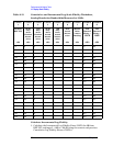
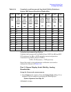
1. Perform step 2 to step 4 for each measurement value in
Table 2-13.
2. Set the 1 dB and 10 dB step attenuators as indicated in Column 2
and Column 3 of Table 2-13 for the various dB from REF LVL
settings.
For settings of –64 dB and lower, press the following keys:
BW/Avg, Average (On)
5, Enter
3. Press Peak Search (or Search) on the analyzer and record the marker
delta (
∆ Mkr1) reading in Column 7 of Table 2-13.
4. Calculate the Cumulative Log Fidelity Error (CLFE) as follows, and
record the result in the performance verification test record as
indicated in Column 8 of Table 2-13:
CLFE Total Actual Attenuation Mkr∆ Reading Total Actual Atten 0 dB from Ref Level()–+=
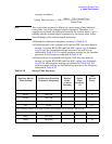
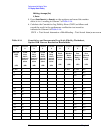
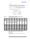
Table 2-13 Cumulative and Incremental Log Scale Fidelity Worksheet,
Analog Resolution Bandwidths Measured at 3 kHz
Column
1
Column
2
Column
3
Column
4
Column
5
Column
6
Column
7
Column
8
Column
9
dB from
REF LVL
(dB)
10 dB
Step
Atten
Nominal
Attenu-
ation
(dB)
1 dB
Step
Atten
Nominal
Attenu-
ation
(dB)
10 dB
Step
Atten
Actual
Attenu-
ation
(dB)
1 dB
Step
Atten
Actual
Attenu-
ation
(dB)
Total
Actual
Attenu-
ation
(dB)
Marker
Delta
(∆ Mkr1)
Reading
(dB)
Test
Record
Entry –
CLFE
(dB)
Test
Record
Entry –
ILFE
(dB)
0 (Ref) 0 0 0 (Ref) 0 (Ref) NA