


Chapter 2 371
Performance Verification Tests
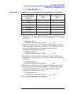
48. Tracking Generator Non-Harmonic Spurious Outputs: Agilent E4402B, E4403B, E4404B,
E4405B, E4407B, and E4408B (Option 1DN)
1. Complete this step only if more than two hours have elapsed since
performing a front-panel calibration of the microwave analyzer.
The microwave analyzer should be allowed to warm up for at least 30
minutes before proceeding.
Complete a front-panel calibration of the microwave analyzer by
performing the following steps:
a. Preset the microwave analyzer.
b. Connect a BNC cable between CAL OUTPUT and 50
Ω Input.
c. Press
CAL, REALIGN LO & IF.
d. Set
FREQUENCY, 300 MHz.
e. Set
SPAN, 20 MHz.
f. Set
AMPLITUDE, –10 dBm.
g. Press
PEAK SEARCH.
h. Press
CAL, REF LVL ADJ and use the ⇑ ⇓ arrows to adjust the DAC
value to a marker amplitude reading of
−10 dBm. Press STORE
REF LVL
.
i. Disconnect the BNC cable from between the CAL OUTPUT and
50
Ω Input.
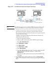
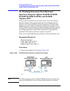
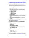
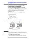
2. Use the Type-N cable to connect the RF Input to the RF OUT of the
tracking generator as shown in Figure 2-68. Do not connect to the RF
Input of the microwave analyzer yet.
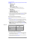
3. Press
Preset on the analyzer under test. Press the Factory Preset
softkey, if it is displayed. Set the analyzer by pressing the following
keys:
FREQUENCY, 50 MHz
SPAN
, Zero Span
BW/Avg
, 30 kHz
System, Alignments, Auto Align, Off
Marker
Source, Tracking Peak
(wait for the Peaking message to appear)
Source, Amplitude On, –2 dBm
Single
4. Set the microwave analyzer by pressing the following keys:
•
SPAN, 100 kHz
• AMPLITUDE, 5 dBm
•
AMPLITUDE, Attenuation, 20 dB
• AMPLITUDE, LOG dB/DIV, 10 dB
5. Disconnect the Type-N cable from between the analyzer RF INPUT
and the tracking generator RF OUT. Refer to Figure 2-68 to connect
the Type-N cable from the analyzer RF OUT to the microwave