


294 Chapter 2
Performance Verification Tests
34. Gain Compression: Agilent E4404B, E4405B, E4407B, and E4408B
34. Gain Compression: Agilent E4404B,
E4405B, E4407B, and E4408B
This test verifies the ability of the analyzer to measure relatively
low-amplitude signals in the presence of higher-amplitude signals. Gain
compression is measured by applying two signals, separated by a
defined amount in frequency. The higher-amplitude signal is set to yield
the specified total power at the input mixer (the power at the input
mixer is defined as the input power level minus the input attenuation).
The lower-amplitude signal is set at least 35 dB below the
higher-amplitude signal, such that its power does not significantly add
to the total power. The higher-amplitude signal is turned off and the
lower-amplitude signal level is measured. This is the uncompressed
amplitude.
The higher-amplitude signal is turned on and the amplitude of the
lower-amplitude signal is again measured. This is the compressed
amplitude. The difference between the uncompressed and compressed
amplitude is the measured gain compression.
There are no related adjustment procedures for this performance test.
Equipment Required
Synthesized sweeper (2 required)
Power meter, dual channel
Microwave power sensor
Directional bridge
Directional coupler
Cable, BNC, 120-cm (48-in)
Cable, APC 3.5 (m) (2 required)
Adapter, Type-N (m) to Type-N (m)
Adapter, Type-N (m) to APC 3.5 (f) (3 required)
Adapter, Type-N (m) to SMA (m)
Additional Equipment for Option BAB
Adapter, Type-N (m), to APC 3.5 (f)
Procedure
1. Zero and calibrate the power meter and power sensor combination in
log mode (power reads out in dBm) as described in the power meter
operation manual.
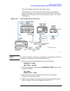
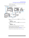
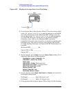
2. Connect the equipment as shown in Figure 2-50, with the load port
of the directional bridge connected to the power sensor. The
directional bridge should be used for measurements of frequencies