


178 Chapter 2
Performance Verification Tests
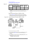
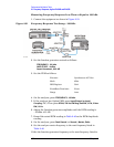
23. Frequency Response, Agilent E4402B and E4403B
as marker (Mkr1) Amplitude.
24.Repeat step 18 through step 23 for frequencies between 100 kHz and
10 MHz.
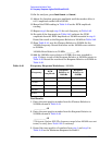
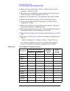
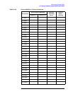
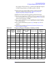
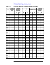
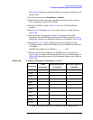
25.Copy the Splitter Tracking Errors from Table 2-44 into Table 2-45.
26.Calculate the Flatness Error for each frequency in Table 2-45 as
follows:
For example, if marker (Mkr1) Amptd is –10.32 dBm, Current
Channel B is –10.2 dBm and Splitter Tracking Error is 0.18 dB,
Flatness Error would be –0.30 dB.
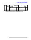
27.Record the Flatness Error for 50 MHz below as the 50 MHz
Ref Amptd:
50 MHz Ref Amptd: __________
28.Calculate the setup change error (error due to changing the test
setup from using a synthesized sweeper to using a function
generator) as follows:
a. Record the Flatness Error from Table 2-45 at 10 MHz using the
function generator as FlatError
FG
:
FlatError
FG
=__________ dB
b. Record the Flatness Error from Table 2-45 at 10 MHz using the
synthesized sweeper as FlatError
SS
:
FlatError
SS
=__________ dB
c. Subtract FlatError
SS
from FlatError
FG
and record the result as
the Setup Change Error:
Setup Change Error =__________ dB
29.For frequencies less than 10 MHz calculate the Flatness Relative to
50 MHz for each frequency in Table 2-45 as follows:
For example, if Flatness Error is –0.30 dB, 50 MHz Ref Amptd is
0.15 dB and Setup Change Error is –0.19 dB, Flatness Relative to 50
MHz would be –0.26 dB.
30.For frequencies 10 MHz and greater, calculate the Flatness Relative
to 50 MHz for each frequency in Table 2-45 as follows:
Flatness Error Mkr1 Amptd
dBm
Current Channel B
dBm
Splitter Tracking Error
dB
––=
Setup Change Error FlatError
FG
FlatError
SS
–=
Flatness Relative to 50 MHz Flatness Error 50 MHz Ref Amptd– Setup Change Error–=
Flatness Relative to 50 MHz Flatness Error 50 MHz Ref Amptd–=