


86 Chapter 2
Performance Verification Tests
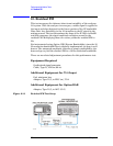
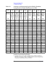
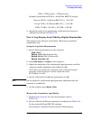
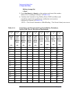
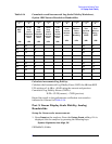
12. Display Scale Fidelity
12. Display Scale Fidelity
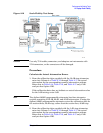
A 50 MHz CW signal is applied to the input of the analyzer through two
calibrated step attenuators. The attenuators are the amplitude
reference standard. The source is adjusted for a response at the
reference level. The attenuators are then set to achieve a nominal
amplitude below the reference level. The analyzer amplitude marker is
compared to the actual total attenuation to determine the scale fidelity
error.
The test is performed in both log and linear amplitude scales.
The related adjustment for this performance test is “IF Amplitude.”
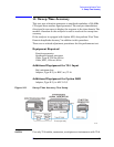
Equipment Required
Synthesized signal generator
1 dB step attenuator
10 dB step attenuator
6 dB fixed attenuator (2 required)
Attenuator switch driver (if programmable step attenuators are
used)
Cable, Type-N 152-cm (60-in) (2 required)
Cable, BNC 122-cm (48-in)
Attenuator interconnect kit
Additional Equipment for 75 Ω Input
50 Ω to 75 Ω minimum loss pad
Adapter, Type-N (f), to BNC (m), 75
Ω
Additional Equipment for Option BAB
Adapter, Type-N (f), to APC 3.5 (f)