


232 Chapter 2
Performance Verification Tests
27. Frequency Response (Preamp On): Agilent E4404B, E4405B, and E4407B
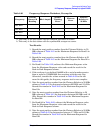
Channel B of the power meter. This will be the “buried” sensor.
2. Zero and calibrate both power sensors.
3. On the power meter, set the Channel A calibration factor to the
calibration factor of the reference sensor at 1 MHz.
4. On the power meter, set the Channel B calibration factor to 100%.
Do not change this calibration factor during this test.
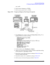
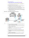
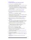
5. Connect the equipment as shown in Figure 2-40. Use the function
generator as the source. Note that the reference sensor connects to
the 20 dB fixed attenuator.
Figure 2-40 Source/Splitter Characterization Setup
6. Set the function generator frequency to 1 MHz and amplitude to
446 mV rms (approximately 6 dBm).
7. Adjust the source amplitude to obtain a Channel A power meter
reading of –20 dBm
±0.1 dB.
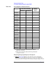
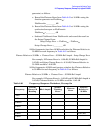
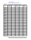
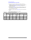
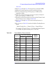
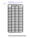
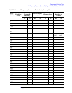
8. Record the Channel A and Channel B power meter readings in
Table 2-63.
9. Tune the source to the next frequency in Table 2-63.
10.On the power meter, set the Channel A calibration factor to the
calibration factor of the reference sensor for the current source
frequency.
11.Adjust the source amplitude to obtain a Channel A power meter
reading of –20 dBm
±0.1 dB.
12.Record the Channel A and Channel B power meter readings in