


Chapter 2 137
Performance Verification Tests
18. Absolute Amplitude Accuracy (Reference Settings): Agilent E4402B, E4403B, E4404B,
E4405B, E4407B, and E4408B
Part 1. Splitter/Attenuator Characterization
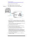
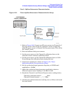
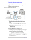
Figure 2-19 Power Splitter/Attenuator Characterization Setup
1. Refer to Figure 2-19. Connect one RF power sensor to Channel A of
the power meter. This will be the “reference” sensor. Connect the
other RF power sensor to Channel B of the power meter. This will be
the “buried” sensor.
2. Zero and calibrate both power sensors.
3. On the power meter, set the Channel A calibration factor to the
reference sensor’s reference calibration factor.
4. On the power meter, set the Channel B calibration factor to 100%.
Do not change this calibration factor during this test.
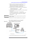
5. Connect the equipment as shown in Figure 2-19, “Power
Splitter/Attenuator Characterization Setup,”.
6. Set the synthesized signal generator frequency to 50 MHz and
amplitude to +12 dBm
7. Adjust the synthesized signal generator amplitude to obtain a
Channel A power meter reading of
−14 dBm ±0.1 dB.
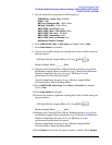
8. Record the Channel A and Channel B power meter readings below:
Channel A (reference sensor): ________ dBm
Channel B (buried sensor): ________ dBm
9. Calculate the splitter/attenuator tracking error as follows and record
the result below: