


Chapter 2 151
Performance Verification Tests
20. Overall Absolute Amplitude Accuracy: Agilent E4402B, E4403B, E4404B, E4405B, E4407B,
and E4408B
4. Zero and calibrate the power meter and power sensor connected to
Channel A of the power meter.
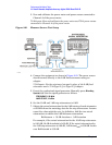
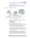
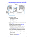
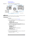
5. Connect the equipment as shown in Figure 2-23. The power sensor
should connect directly to the 6 dB fixed attenuator using an
adapter.
Figure 2-23 Measure Source Test Setup
6.
Preset the synthesized signal generator. Manually press Blue Key,
Special, 0, 0
. Set the signal generator as follows:
FREQUENCY, 50 MHz
AMPLITUDE, 12 dBm
7. Set the 10 dB and 1 dB step attenuators to 0 dB.
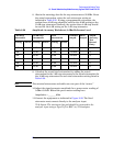
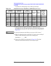
8. Obtain the actual attenuation for the 0 dB setting of each attenuator
at 50 MHz from the metrology data for the step attenuators. In some
cases this value might be zero, by definition. Add the two actual
attenuations to obtain the 0 dB reference attenuation.
For example, if the actual attenuation for the 10 dB step attenuator
is 0.03 dB, 10 dB Actual
0dB
is 0.03 dB. If the actual attenuation for
the 1 dB step attenuator is 0.02 dB, 1 dB Actual
0dB
is 0.02 dB. In this
case RefAtten
0dB
is 0.05 dB.
9. Obtain the metrology data for the step attenuators at 50 MHz. Enter
the actual attenuation values for each attenuator setting as
indicated in Table 2-34. If using a programmable attenuator, the
section three 40 dB step should be used for the 40 dB setting on the
10 dB step attenuator. Similarly, the section three 4 dB step should
RefAtten
0dB
10 dB Actual
0dB
1 dB Actual
0dB
+=