


162 Chapter 2
Performance Verification Tests
22. Frequency Response: Agilent E4401B and E4411B
22. Frequency Response: Agilent E4401B and
E4411B
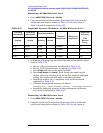
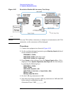
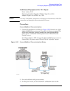
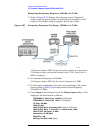
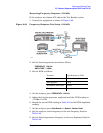
This test measures the amplitude error of the analyzer as a function of
frequency. To measure frequencies of 100 kHz and greater, the output of
a signal generator is fed through a power splitter to a power sensor and
the analyzer.
To measure frequencies below 100 kHz, a digital voltmeter (DVM) with
a 50
Ω load replaces the power sensor and a function generator is used
as the source.
For improved amplitude accuracy, the power splitter is characterized
using a power sensor (the “reference” sensor) connected to one power
splitter output port. The other power splitter output port connects to
the “buried” sensor; it is not removed from the power splitter. Once the
characterization is done, the reference sensor is removed and replaced
by the analyzer.
This procedure does not test frequency response with the optional
preamplifier (Option 1DS) turned on. If the analyzer is equipped with
Option 1DS, also perform the “Frequency Response, Preamp On”
procedure.
The related adjustment for this performance test is “Frequency
Response.”
Analyzers with 75
Ω inputs are tested down to 1 MHz only.
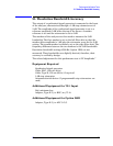
Equipment Required
Synthesized signal generator
Function generator
Power meter
RF power sensor, (2 required)
RF Power splitter
Digital multimeter
Adapter, Type-N (m) to Type-N (m)
Adapter, Type-N (m) to BNC (f)
Dual banana plug to BNC (f)
BNC Tee (BNC f,m,f)
Cable, BNC, 120-cm (48-in) (2 required)
Cable, Type-N, 183-cm (72-in)
Termination, 50
Ω, BNC (m)