


424 Chapter 2
Performance Verification Tests
59. Comms Absolute Power Accuracy (Options BAC or BAH)
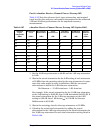
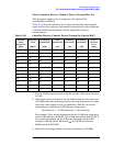
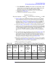
4. Calculate the actual total attenuation by adding the actual
attenuation for the 1 dB step attenuator to the actual attenuation for
the 10 dB step attenuator for each total attenuation setting listed in
Table 2-132.
NOTE The external attenuators and cables are now part of the “source.”
5. Set the analyzer as follows:
FREQUENCY, Center Freq, 50 MHz
SPAN, 0 kHz
BW/Avg, Res BW, 10 kHz
BW/Avg
, Video BW, 10 kHz
AMPLITUDE
, More, Y-Axis Units (or Amptd Units), dBm
AMPLITUDE, Ref Level, –20 dBm
AMPLITUDE, Attenuation, 0 dB
AMPLITUDE, More, Int Preamp On
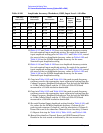
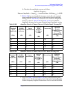
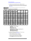
6. Perform the following steps for each of the “Nominal Input
Amplitude” values listed in Table 2-131.
a. Set the 1 dB step attenuator as indicated.
b. Set the 10 dB step attenuator as indicated.
c. Set the analyzer reference level as indicated.
d. Set the analyzer input attenuation as indicated.
e. Press
Single and wait for the sweep to finish.
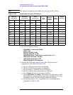
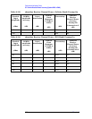
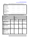
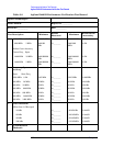
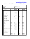
Table 2-132 Amplitude Accuracy Worksheet
1 dB Step
Attenuator
10 dB Step
Attenuator
Total
Attenuation
Ref Level
Nominal
Input
Amptd
Meas
Amptd
Amptd
Accy
Setting Actual Setting Actual Setting Actual
0 dB 40 dB 40 dB –20 dBm –40 dBm
0 dB 40 dB 40 dB –40 dBm –40 dBm
0 dB 60 dB 60 dB –40 dBm –60 dBm
0 dB 60 dB 60 dB –60 dBm –60 dBm
0 dB 70 dB 70 dB –50 dBm –70 dBm
0 dB 70 dB 70 dB –70 dBm –70 dBm
0 dB 80 dB 80 dB –60 dBm –80 dBm
0 dB 80 dB 80 dB –80 dBm –80 dBm
0 dB 90 dB 90 dB –70 dBm –90 dBm
0 dB 90 dB 90 dB –90 dBm –90 dBm
0 dB 100 dB 100 dB –80 dBm –100 dBm
0 dB 100 dB 100 dB –100 dBm –100 dBm