


Chapter 2 129
Performance Verification Tests
17. Absolute Amplitude Accuracy (Reference Settings): Agilent E4401B and E4411B
17. Absolute Amplitude Accuracy (Reference
Settings): Agilent E4401B and E4411B
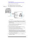
A power sensor (the “buried sensor”), power splitter, and attenuator
combination is characterized at 50 MHz using a second power sensor
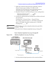
(the “reference sensor”). The attenuator is then connected to the input
of the analyzer and the signal generator power level is adjusted for the
appropriate level at 50 MHz. A complete auto alignment is performed.
The 50 MHz signal is then measured with the spectrum analyzer. The
difference between the power meter reading (corrected for the
splitter/attenuator tracking error) and spectrum analyzer readings is
calculated.
For analyzers with 75
Ω inputs, a minimum loss pad is used between the
attenuator and the analyzer, and a lower-value attenuator is used.
For analyzers with Option 1DS, Preamplifier, the test is repeated with
preamp on
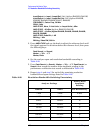
Equipment Required
Synthesized signal generator
Power meter
RF power sensor (2 required)
Power splitter
20 dB attenuator
Cable, Type-N, 152-cm (60-in)
Adapter, Type-N (m) to Type-N (m)
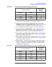
Additional Equipment for 75 Ω Input
Power sensor, 75 Ω
Adapter, mechanical, Type-N (f), 75 Ω to Type-N (m) 50 Ω
Pad, minimum loss
Adapter, Type-N (f), to BNC (m), 75
Ω
10 dB attenuator
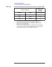
Procedure
This performance test consists of three parts:
Part 1. Splitter/Attenuator Characterization
Part 2. Absolute Amplitude Accuracy, Preamp Off
Part 3. Absolute Amplitude Accuracy, Preamp On (Option 1DS)
Parts 1 and 2 should be performed on all Agilent Spectrum Analyzers.
Part 3 should be performed only on ESA-E Series Spectrum Analyzers