


Chapter 2 215
Performance Verification Tests
25. Frequency Response (Preamp On): Agilent E4401B
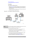
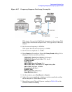
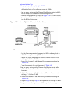
75 Ω inputs: Connect the reference sensor to the power splitter and
attenuator using the minimum loss pad.
6. Set the source frequency to 100 kHz and amplitude to 6 dBm.
75
Ω inputs: Set the source frequency to 1 MHz and amplitude to
12 dBm.
7. Adjust the source amplitude to obtain a Channel A power meter
reading of –20 dBm
±0.1 dB.
8. Record the Channel A and Channel B power meter readings in
Table 2-57.
9. Tune the source to the next frequency in Table 2-57.
10.On the power meter, set the Channel A calibration factor to the
calibration factor of the reference sensor for the current source
frequency.
11.Adjust the source amplitude to obtain a Channel A power meter
reading of –20 dBm
±0.1 dB.
12.Record the Channel A and Channel B power meter readings in
Table 2-57.
13.Repeat step 9 through step 12 for each frequency in Table 2-57.
14.For each entry in Table 2-57, calculate the Splitter Tracking Error as
follows:
For example, if Channel A Power is –20.3 dBm and Channel B power
is –0.23 dBm, the splitter tracking error is –20.07 dB.
NOTE Tracking errors are nominally –25.7 dB when using the minimum loss
pad.
Splitter Tracking Error Channel A Power Channel B Power–=
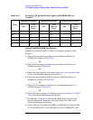
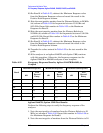
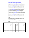
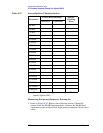
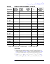
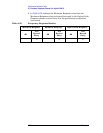
Table 2-57 Source/Splitter Characterization
Frequency
Power Meter Reading Splitter
Tracking
ErrorChannel A Channel B
100 kHz
a
500 kHz
a
1 MHz
5 MHz
10 MHz