


Chapter 2 189
Performance Verification Tests
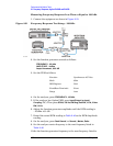
24. Frequency Response, Agilent E4404B, E4405B, E4407B, and E4408B
power meter reading of –10 dBm ±0.1 dB.
7. Record the function generator amplitude setting, and both the
Channel A and Channel B power meter readings in Table 2-49.
8. Tune the source to the next frequency in Table 2-49.
9. On the power meter, set the Channel A calibration factor to the
calibration factor of the reference sensor for the current source
frequency.
10.Adjust the source amplitude to obtain a Channel A power meter
reading of –10 dBm
±0.1 dB.
11.Record the source amplitude setting, and both the Channel A and
Channel B power meter readings in Table 2-49.
12.Repeat step 8 through step 11 for frequencies up through 10 MHz.
13.Replace the function generator with the synthesized sweeper.
14.Set the synthesized sweeper CW frequency to 10 MHz and the
amplitude to –4 dBm.
15.Adjust the synthesized sweeper power level to obtain a Channel A
power meter reading of –10 dBm
±0.1 dB.
16.Record the synthesized sweeper power level and both the Channel A
and Channel B power meter readings in Table 2-49.
17.Repeat step 8 through step 11 for each remaining frequency in Table
2-49.
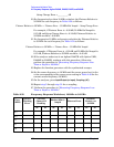
18.For each entry in Table 2-49, calculate the Splitter Tracking Error as
follows:
For example, if Channel A Power is –10.05 dBm and Channel B
Power is –10.23 dBm, the Splitter Tracking Error is 0.18 dB.
Splitter Tracking Error Channel A Power Channel B Power–=
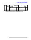
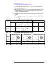
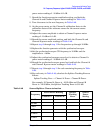
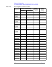
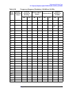
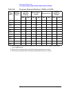
Table 2-49 Source/Splitter Characterization
Frequency
Power Meter Reading Splitter
Tracking
Error
Source
Power
SettingChannel A Channel B
100 kHz
500 kHz
1 MHz
5 MHz
10 MHz
a
10 MHz
b