


Chapter 2 213
Performance Verification Tests
25. Frequency Response (Preamp On): Agilent E4401B
25. Frequency Response (Preamp On):
Agilent E4401B
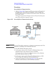
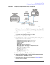
This test measures the amplitude error of the analyzer as a function of
frequency. The output of a source is fed through a power splitter to a
power sensor and the analyzer. The power level of the source is adjusted
at 50 MHz to place the displayed signal at approximately –32 dBm. At
each new source frequency and analyzer center frequency, the power
level of the source is adjusted to place the signal at approximately
–32 dBm.
For improved amplitude accuracy the power splitter is characterized
using a power sensor (the “reference” sensor) connected to one power
splitter output port. The other power splitter output port connects to
the “buried” sensor; it is not removed from the power splitter. Once the
characterization is done, the reference sensor is removed and replaced
by the analyzer.
Analyzers with 75
Ω inputs are tested down to 1 MHz only.
This procedure only tests frequency response with the optional
preamplifier (Option 1DS) turned on. Perform the “Frequency
Response” procedure to test all other frequency response specifications.
The related adjustment for this performance test is “Frequency
Response.”
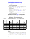
Equipment Required
Synthesized signal generator
Power meter
RF power sensor (2 required for 50
Ω inputs)
20 dB fixed attenuator
Power splitter
Cable, Type-N (m), 183 cm
Cable, BNC, 120 cm
Adapter, Type-N (m) to Type-N (m)
Adapter, Type-N (m) to BNC (f)
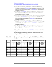
Additional Equipment for 75 Ω Input
Power sensor, 75 Ω
Minimum Loss Pad, Type-N (m) 50 Ω to Type-N (f) 75 Ω
Adapter, Type-N (m) to BNC (m), 75 Ω