


312 Chapter 2
Performance Verification Tests
36. Displayed Average Noise Level: Agilent E4402B and E4403B
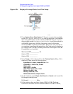
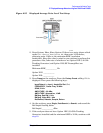
Figure 2-54.
17.Disconnect the BNC cable and adapter from the AMPTD REF OUT
and the 50
Ω Input.
18.If the analyzer has Option 1DN, 50
Ω tracking generator, do the
following:
a. On the analyzer, press
BW/Avg, Res BW, 1 kHz.
b. Press
Source, Amplitude, 0 dBm.
c. Connect a 50
Ω termination to the RF OUT 50 Ω.
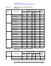
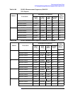
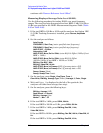
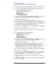
Measurement Sequence
The following DANL Measurement Sequence table lists the procedures
to be performed and the parameters to be used in each procedure. Also
listed in the table are test record entry numbers for recording the
results in the performance verification test record.
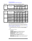
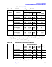
1. Perform all of the following steps (through step 7) that apply to your
analyzer using the appropriate subsets in Table 2-85 (for E4402B) or
Table 2-86 (for E4403B). Then record the display line amplitude
setting as the indicated Test Record entry in the performance
verification test record.
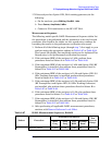
2. If the minimum RBW of the analyzer is 1 kHz, perform those
procedures listed as Subset A in Table 2-85 or Table 2-86.
3. If the minimum RBW of the analyzer is 1 kHz and Option 1DS (RF
Preamplifier) is installed, also perform those procedures listed in
Subset B in Table 2-85.
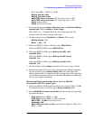
4. If the minimum RBW of the analyzer is 100 Hz or 10 Hz and Option
1DN (3.0 GHz Tracking Generator) is installed, perform those
procedures listed in Subset A in Table 2-85 or Table 2-86.
5. If the minimum RBW of the analyzer is 10 Hz and both Option 1DS
(RF Preamplifier) and Option 1DN (3.0 GHz Tracking Generator)
are installed, also perform those procedures listed in Subset B in
Table 2-85.
6. If the minimum RBW of the analyzer is 100 Hz or 10 Hz, perform
those procedures listed in Subset C in Table 2-85 or Table 2-86.
7. If the minimum RBW of the analyzer is 10 Hz and Option 1DS (RF
Preamplifier) is installed, also perform those procedures listed in