


366 Chapter 2
Performance Verification Tests
47. Tracking Generator Non-Harmonic Spurious Outputs: Agilent E4401B and E4411B (Option
1DN or 1DQ)
FREQUENCY, 50 MHz
SPAN
, Zero Span
BW/Avg
, 30 kHz
Marker
Source
, Amplitude On, 0 dBm
Source, Amplitude On, 42.76 dBmV (75 Ω Option only)
3. Set the microwave analyzer by pressing the following keys:
•
SPAN, 100 kHz
• AMPLITUDE, 5 dBm
•
AMPLITUDE, 0 dBm (75 Ω Option only)
•
AMPLITUDE, ATTEN, 20 dB
•
AMPLITUDE, LOG dB/DIV, 10 dB
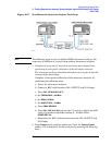
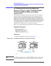
4. Disconnect the Type-N cable from between the analyzer RF INPUT
and the tracking generator RF OUT. Refer to Figure 2-67 to connect
the Type-N cable from the analyzer RF OUT to the microwave
analyzer 50
Ω Input.
Measuring Fundamental Amplitudes
Perform the following two steps for each fundamental frequency in
Table 2-101.
1. Set the analyzer under test center frequency to the fundamental
frequency listed in Table 2-101 and press
Single to activate a single
sweep. Set the microwave analyzer to the same frequency.
2. On the microwave analyzer, press
PEAK SEARCH. Press MKR →,
MARKER → REF LVL. Wait for another sweep to finish. Press PEAK
SEARCH
. Record the marker amplitude reading in Table 2-101 as the
Fundamental Amplitude.
Measuring Non-Harmonic Responses
1. On the analyzer under test, set the center frequency to the initial
value indicated in the first row of Table 2-101. Press
Single on the
analyzer to trigger a single sweep.
2. Set the microwave analyzer Start Freq, Stop Freq, and Res BW as
indicated in the first row of Table 2-102.
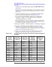
Table 2-101 Tracking Generator Fundamental Response Worksheet
Fundamental Frequency
Fundamental Amplitude
(dBm)
10 MHz
750 MHz
1.5 GHz