


132 Chapter 2
Performance Verification Tests
17. Absolute Amplitude Accuracy (Reference Settings): Agilent E4401B and E4411B
FREQUENCY, 50 MHz
AMPLITUDE
, –1 dBm (50 Ω Input only)
AMPLITUDE, –2.3 dBm (75 Ω Input only)
RF ON
AM OFF
FM OFF
2. Press Preset on the analyzer. (Press the Factory Preset softkey, if it is
displayed.)
3. Press
System, Alignments, Align Now, All. Wait for the auto alignment
to finish. Press
System, Alignments, Auto Align, Off.
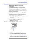
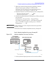
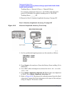
4. Refer to Figure 2-18. Disconnect the reference sensor from the fixed
attenuator. Connect the fixed attenuator or minimum loss pad to the
input of the analyzer using an adapter. Do not use a cable.
75
Ω Input: Disconnect the reference sensor from the minimum loss
pad. Connect the minimum loss pad to the input of the analyzer using
an adapter, do not use a cable.
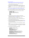
5. Calculate the ideal buried sensor reading by subtracting the
Tracking Error recorded in step 9 of Part 1 from the ideal input level
to the analyzer, as indicated in the table below:
Ideal Buried Sensor Reading = Ideal Input Level
− Tracking Error
6. Adjust the synthesized signal generator to obtain the Ideal Buried
Sensor Reading calculated above
±0.1 dB.
7. Calculate the Corrected Power Meter Reading by adding the current
power meter reading to the Tracking Error recorded in Part 1, step 9
and record the result below:
Corrected Power Meter Reading = Power Meter Reading + Tracking
Error
Example: If the Power Meter Reading is 0.24 dBm and the Tracking
Error is
−20.3 dB, the Corrected Power Meter Reading is −20.06 dBm
Corrected Power Meter Reading ______ dBm
8. Set the analyzer by pressing the following keys:
FREQUENCY, Center Freq, 50 MHz
SPAN, 2 kHz
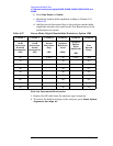
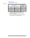
Input
Impedance
Ideal Input
Level
Tracking
Error from
Part 1, step 9
Ideal Buried
Sensor
Reading
50
Ω−27 dBm
75
Ω−24 dBm