


244 Chapter 2
Performance Verification Tests
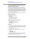
28. Other Input-Related Spurious Responses: Agilent E4401B and E4411B
28. Other Input-Related Spurious Responses:
Agilent E4401B and E4411B
This test measures the ability of the analyzer to reject image and
multiple responses. A synthesized source and the analyzer are set to
the same frequency and the amplitude of the source is set to –20 dBm.
A marker amplitude reference is set on the analyzer. The source is then
tuned to several different frequencies which should generate image and
multiple responses. At each source frequency, the source amplitude is
set to –20 dBm and the amplitude of the response, if any, is measured
using the analyzer marker functions.
There are no related adjustment procedures for this performance test.
Equipment Required
Synthesized signal generator
Power meter
RF power sensor
Adapter, Type-N (f) to APC 3.5 (f)
Adapter, Type-N (f) to Type-N (f)
Cable, Type-N, 152-cm (60-in)
Additional Equipment for 75 Ω Input
Power sensor, 75 Ω
Adapter, Type-N (f), to BNC (m), 75 Ω
Adapter, BNC (m), to BNC (m), 75 Ω
Pad, minimum loss
Procedure
1. Zero and calibrate the power meter and RF power sensor in log mode
(power reads out in dBm), as described in the power meter operation
manual. Enter the 500 MHz calibration factor of the power sensor
into the power meter.
75
Ω Input only: Use a 75 Ω power sensor.
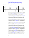
2. Press
Preset on the synthesized sweeper and set the controls as
follows:
CW, 542.8 MHz
POWER LEVEL
, –10 dBm
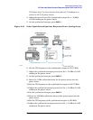
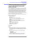
3. Connect the equipment as shown in Figure 2-42 with the output of
the synthesized sweeper connected to the power sensor using an
adapter between the cable and the power sensor.