


354 Chapter 2
Performance Verification Tests
44. Tracking Generator Level Flatness: Agilent E4402B, E4403B, E4404B, E4405B, E4407B,
and E4408B (Option 1DN)
2. Set the analyzer resolution bandwidth to 10 kHz by pressing
BW/Avg, Res BW, 10 kHz.
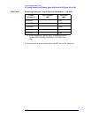
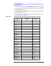
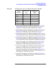
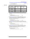
Repeat step 3 through step 7 for each Center Frequency value in
Table 2-98.
3. Set the analyzer center frequency to 9 kHz, by pressing
FREQUENCY,
9 kHz.
4. Press
Single.
5. Record the DVM readout in Table 2-98.
6. Subtract the 100 kHz Level Flatness readout in Table 2-97 from the
100 kHz DVM Readout in Table 2-98 and record as the DVM Offset
at 100 kHz.
DVM Offset at 100 kHz ___________ dB
For example, if the Level Flatness reading from Table 2-97 is
0.7 dB and the DVM Readout from Table 2-98 is
−0.53 dBm, the
DVM offset would be
−1.23 dB.
7. Add the DVM Offset at 100 kHz from step 6, above, to each of the
DVM Readouts in Table 2-98 and record as the Corrected Level
Flatness in Column 3.
For example, if the DVM Readout from Table 2-98 is 0.22 dBm,
and the DVM Offset is
−1.23 dB, the Corrected Level Flatness
would be
−1.01 dB.
8. Press
System, Alignments, Auto Align, All.
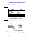
Set to 50
Ω impedance
SMATH 10
a
Set to dBm
MATH 5
a
Set to Synchronous
SETACV 3
a
Sub-sampled mode
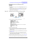
a. To set the Agilent 3458A multimeter functions from the
front panel, press the blue shift key, then Recall State (T)
key. Use the
⇑ (up) and ⇓ (down) arrows to select the
appropriate function, then enter the value from the
numeric keypad and press enter.
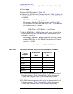
Parameter Setting
DVM Offset DVM Readout= Level Flatness–
Corrected Level Flatness DVM Readout= DVM Offset+