


318 Chapter 2
Performance Verification Tests
37. Displayed Average Noise Level: Agilent E4404B and E4405B
6. If the analyzer has a minimum RBW of 1 kHz or has Option 1DN
(3.0 GHz Tracking Generator) installed then continue with step 7.
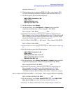
7. On the analyzer, press the following keys:
AMPLITUDE, Attenuation, 0 dB
SPAN, 20 kHz
BW/Avg, Res BW, 1 kHz
BW/Avg, Video BW, 30 Hz
8. On the analyzer, press Single, Peak Search (or Search) and record the
amplitude reading below as Meas Amptd (1 kHz RBW).
Meas Amptd (1 kHz RBW)____________ dB
9. Calculate the necessary reference level offset by subtracting the
Meas Amptd in step 8 from the Ref Amptd in step 4. If the calculated
Ref Lvl Offset is greater than 0.05 dB or less than –0.05 dB, record
the Ref Lvl Offset value below. Otherwise, enter 0.
Ref Lvl Offset (1 kHz RBW)____________ dB
10.If the analyzer is not equipped with Option 1DR, continue with step
14.
11.On the analyzer, press the following keys:
AMPLITUDE, Attenuation, 0 dB
SPAN, 500 Hz
BW/Avg, Res BW, 10 Hz
BW/Avg, Video BW, 1 Hz
12.On the analyzer, press Single, Peak Search (or Search) and record the
amplitude reading below as Meas Amptd (10 Hz RBW).
Meas Amptd (10 Hz RBW)____________ dB
13.Calculate the necessary reference level offset by subtracting the
Meas Amptd in step 12 from the Ref Amptd in step 4. If the
calculated Ref Lvl Offset is greater than 0.05 dB or less than –0.05
dB, record the Ref Lvl Offset value below. Otherwise, enter 0.
Ref Lvl Offset (10 Hz RBW)____________ dB
14.On the analyzer, press
Input, Amptd Ref Out (Off), then AMPLITUDE,
More, Ref Lvl Offst
, and enter the value recorded in step 8.
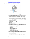
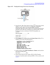
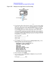
15.Connect the 50
Ω termination to the analyzer input as shown in
Figure 2-55.
16.Disconnect the BNC cable and adapter from the AMPTD REF OUT
and the 50
Ω Input.
Ref Lvl Offset (1 kHz RBW) Ref Amptd Meas Amptd (1 kHz RBW)–=
Ref Lvl Offset (10 Hz RBW) Ref Amptd Meas Amptd (10 Hz RBW)–=