


8-17
Cisco 12000/10700 v3.1.1 Router Manager User Guide
OL-4455-01
Chapter 8 Interface Configuration
POS Interface Configuration
POS Interface Configuration Window—Detailed Description
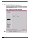
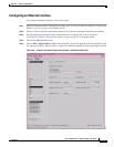
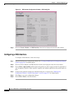
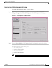
The POS Interface Configuration window contains one tab, POS Config.
POS Config Tab
The POS Config tab (see Figure 8-6) contains four areas: General, SONET Overhead, Alarm Reporting
and Threshold, and Alarm Reporting.
General
The General area contains the following fields:
POS SPE Scrambling—Enable or disable POS SPE scrambling. Scrambling is similar to encrypting. The
enabled option is selected by default.
Loopback—Choose the loopback mode. The following options are available:
Internal—Packets are transmitted back to the source to test the interface functionality and ensure
that packets transmitted through the interface reach the destination without data loss.
Line—Restricts connection status (success or failure) messages from being received.
Disabled—Disables the loopback mode.
Clock Source—Choose a clock source from the available options. There is a clock in every device, which
measures the speed of the device. This can either be Internal (within the device) or Line (network clock).
Keepalive—Set keepalive period. The system sends packets after this interval to know if the interface or
the network is up for routing packets. By default this interval is 10 seconds.
POS Framing—Choose the type of POS framing, SDH or SONET.
Encapsulation—Select HDLC, PPP or FRAME-RELAY encapsulation type.
Cyclic Redundancy Check—Choose an option for cyclic redundancy check. Cyclic redundancy checks
consists of 16 or 32 bit verification code which has to be same at both the transmitting and receiving
ends to ensure the packets sent are received in full without loss of data. By default, it is 32 bit code.
SONET Overhead
The Sonet Overhead area contains the following fields:
Path Signal Identifier—Permissible values range from 0 to 255.
Section Trace Byte—Permissible values range from 0 to 255.
Payload Pointer Byte—Choose an option for payload pointer byte from the drop down menu.
Permissible values range from 0 to 3.
Alarm Reporting & Threshold
The Alarm Reporting & Threshold area allows you to configure and enable alarms generated by the
system. This area contains the following fields:
B1 BER Threshold Crossing Alarm (TCA)—Set threshold limits for the system to prompt appropriate
B1 BER TCA threshold alarm messages. The field beside this value displays the threshold for the B1
BER TCA.