


4. Dedicated Options
4 - 12
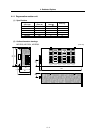
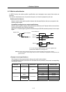
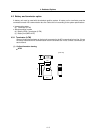
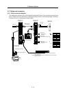
4-4 Relay terminal block (MR-J2CN3TM)
Signals input/output from the CN9 connector on the front of the servo drive unit can be led to the
terminal block. Connect the terminal block to the CN9 connector with an SH21 cable.
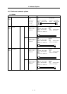
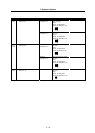
Abbrev. Name Explanation
CN3A Connector 3 input/output A
CN3B Connector 3 input/output B
Connect from the CN3 connector wi
th an SH21 cable. Common for any
connector, so each signal will pass through. When the CN3 control signal
is being used, each signal can be output from the relay terminal block by
relaying through these connectors.
CN3C Connector 3 input/output C
VDD Internal power supply output
This is the 24V power supply output in the drive unit. When using an
internal power supply, use relayed once through the COM terminal.
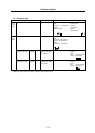
COM Common power supply
Connect VDD when using the drive unit internal power supply. Connect the
+ side of the external power supply when using an external power supply.
EMG External emergency stop input This is the input terminal for external emergency stops.
DOG DI contactor B contact This is not used with the MDS-R.
MO1 Monitor output 1 D/A output ch.1 used to measure the voltage across M01 and LG.
MO2 Monitor output 2 D/A output ch.2 used to measure the voltage across M02 and LG.
PE Plate ground This has the same potential as the drive unit FG or cable shield.
SG 24V power supply ground This is the ground when using digital input/output.
MC Contactor control output This is the output terminal for contactor control.
MBR Motor brake control output This is the output terminal for motor brake control.
LG 5V power supply ground This is the ground when using D/A output.
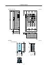
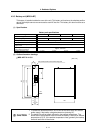
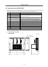
(1) Outline dimension drawings
MR-J2CN3TM
[Unit: mm]
2-ø5.3 (mounting hole)
PE SG MC MBR
VDD COM
EMG DOG MO1
LG
MO2
LG
CN3A CN3B CN3
100
88
41.5
3
75
37.5