


Appendix 1. Cable and Connector Specifications
A1 - 5
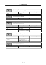
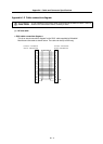
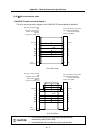
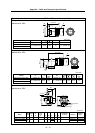
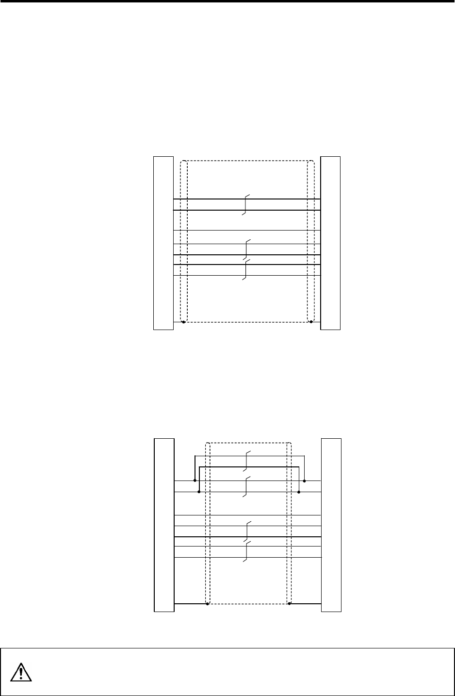
(2) HF□-A51 motor detector cable
< CNV2E-6P/7P cable connection diagram >
This is an actual connection diagram for the CNV2E-6P/7P cable supplied by Mitsubishi.
1
2
9
7
8
3
4
PE
8
5
3
4
6
7
1
2
10
P5(+5V)
LG
BT
SD
SD*
RQ
RQ*
P5(+5V)
LG
-
BT
SD
SD*
RQ
RQ*
SHD
0.5mm
2
Case
grounding
0.2mm
2
0.2mm
2
0.2mm
2
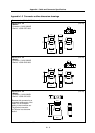
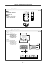
Servo motor detector side connector
Plug: CM10-SP10S-M (Straight)
CM10-AP10S-M (Angle)
Contact: CM10-#22SC
Servo drive unit side connecto
r
(3M)
Receptacle : 36210-0100PL
Shell kit : 36310-3200-008
(MOLEX)
Connector set : 54599-1019
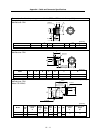
<For 15m or less>
1
2
9
7
8
3
4
PE
8
5
3
4
6
7
1
2
10
P5(+5V)
LG
BT
SD
SD*
RQ
RQ*
P5(+5V)
LG
-
BT
SD
SD*
RQ
RQ*
SHD
0.5mm
2
Case
grounding
0.2mm
2
0.5mm
2
0.2mm
2
0.2mm
2
Servo motor detector side connector
Plug: CM10-SP10S-M (Straight)
CM10-AP10S-M (Angle)
Contact: CM10-#22SC
Servo drive unit side connecto
r
(3M)
Receptacle: 36210-0100PL
Shell kit: 36310-3200-008
(MOLEX)
Connector set: 54599-1019
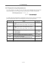
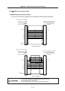
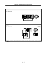
<For 15 to 30m>
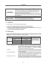
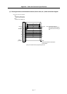
CAUTION
1.
Do not connect anything to pins unless particularly specified when
manufacturing a cable. (Leave OPEN)
2. Contact Mitsubishi when manufacturing a cable longer than 30m.